Jig conveying device

A technology of conveying device and jig, which is applied in the direction of conveyor, transportation and packaging, etc., can solve the problems of jig warping and damage to jig, etc.

Pending Publication Date: 2021-01-12
CHANGZHOU MINGSEAL ROBOT TECH CO LTD
View PDF0 Cites 1 Cited by
  • Summary
  • Abstract
  • Description
  • Claims
  • Application Information

AI Technical Summary

Problems solved by technology

[0004] In order to solve the problem in the related art that clamping and fastening the jig by the positioning device from the side of the jig can easily cause the warping of the jig and damage the jig, this application provides a jig conve...

Method used


Image

  • Jig conveying device
  • Jig conveying device
  • Jig conveying device

Examples


Embodiment Construction

[0031]The exemplary embodiments will be described in detail here, and examples thereof are shown in the accompanying drawings. When the following description refers to the accompanying drawings, unless otherwise indicated, the same numbers in different drawings represent the same or similar elements. The implementation manners described in the following exemplary embodiments do not represent all implementation manners consistent with the present invention. Rather, they are merely examples of devices and methods consistent with some aspects of the present invention as detailed in the appended claims.

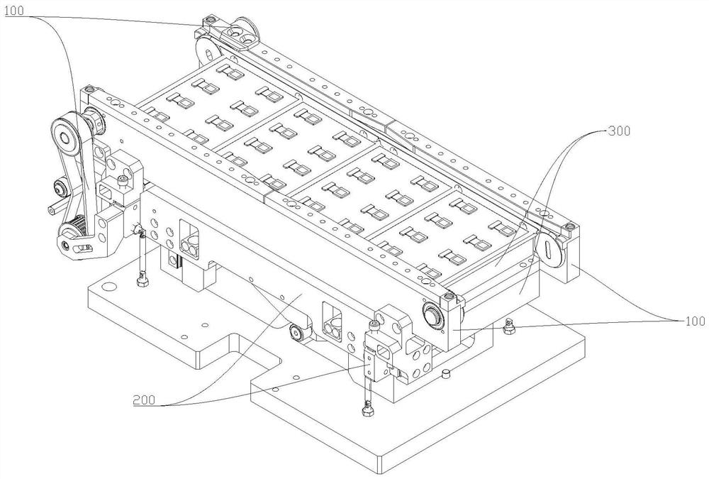
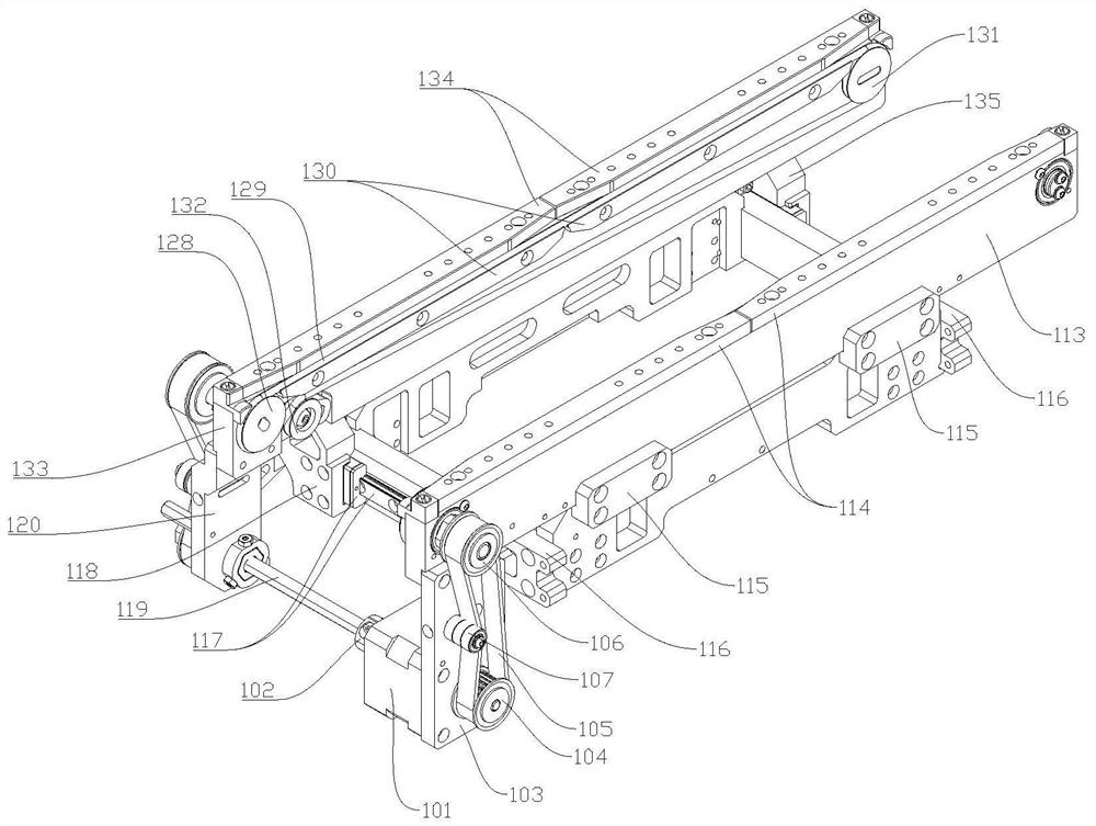
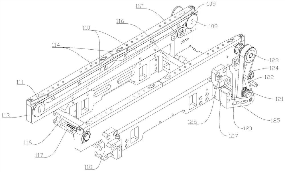
[0032]Please combinefigure 1 withFigure 7 , Is a schematic diagram of the jig conveying device provided in an embodiment of the present application for jig conveying,Figure 7 It is a schematic structural diagram of a jacking mechanism 200 provided in an embodiment of the present application. The jig conveying device includes a conveying mechanism 100, a jacking mechanism 200, and a positi...


PUM


Abstract

The invention discloses a jig conveying device, and belongs to the field of intelligent manufacturing. The jig conveying device comprises a positioning mechanism, a conveying mechanism and a jacking mechanism, wherein the positioning mechanism comprises a fixed seat capable of bearing and fixing a jig, and the fixed seat is provided with a negative pressure adsorption opening used for adsorbing the jig; the conveying mechanism comprises a conveying assembly used for supporting and conveying the jig and a driving mechanism used for driving the conveying assembly to operate, and the conveying mechanism can ascend and descend relative to the positioning mechanism; the jacking mechanism drives the conveying mechanism to be switched between an ascending state and a descending state relative tothe positioning mechanism; when the conveying mechanism drives the conveying assembly to ascend to a first height, the jig is separated from the fixed seat and supported on the conveying assembly; andwhen the conveying mechanism drives the conveying assembly to descend to a second height, the jig is separated from the conveying assembly and supported on the fixed seat, and can be fixed on the fixed seat. The problems that in the prior art, a positioning device clamps and fastens the jig from the side of the jig, the warping of the jig is easily caused, and the jig is damaged are solved.

Description

Technical field[0001]The invention belongs to the field of intelligent manufacturing and relates to a fixture conveying device.Background technique[0002]In the automatic production process, the jig is transported to the processing position by the automatic jig conveying device. After the jig on the processing position is automatically positioned and clamped by the positioning device, the workpiece placed on the jig is processed by the processing equipment deal with.[0003]At present, in mass production, the fixture is clamped and fastened from the side of the fixture by the positioning device, which is likely to cause warpage of the fixture and damage the fixture.Summary of the invention[0004]In order to solve the problem that the positioning device clamps and fastens the jig from the side of the jig in the related art, it is easy to cause the jig to warp and damage the jig, this application provides a jig conveying device.[0005]The jig conveying device includes a positioning mechani...

Claims


Application Information

Patent Timeline
IPC IPC(8): B65G23/04B65G21/12B65G15/12
CPCB65G15/12B65G21/12B65G23/04
Inventor 史晔鑫郜福亮吴红军杨健胡君君曲东升李长峰
Owner CHANGZHOU MINGSEAL ROBOT TECH CO LTD
Why Eureka
Try Eureka