
Rock mass internal fracture visualization three-dimensional similar model device

A technology similar to models and cracks, applied in the direction of measuring devices, applying stable tension/pressure to test material strength, instruments, etc., can solve the problem that it is difficult to realize the evolution characteristics of cracks inside the rock mass, the front and rear width is less than 30cm, and it cannot accurately reflect the stope Problems such as the dynamic expansion of cracks in surrounding rocks, to achieve the effect of improving the accuracy of experimental results, improving accuracy, and reducing friction

Pending Publication Date: 2021-01-12
HEFEI UNIV OF TECH
View PDF0 Cites 2 Cited by
  • Summary
  • Abstract
  • Description
  • Claims
  • Application Information

AI Technical Summary

Problems solved by technology

The vast majority of commercial similar simulation devices are two-dimensional devices, and the front and rear width of traditional two-dimensional similar simulation devices is less than 30cm. The crack expansion of the stope surrounding rock is affected by the boundary, which cannot accurately reflect the dynamic expansion of the actual stope surrounding rock cracks.
However, the existing three-dimensional similar model device is difficult to realize the evolution characteristics and process of cracks inside the rock mass, and the endoscopic device for observing and collecting dynamic images of cracks inside the rock mass has not yet been matched with a similar simulation test device

Method used


Image

  • Rock mass internal fracture visualization three-dimensional similar model device
  • Rock mass internal fracture visualization three-dimensional similar model device
  • Rock mass internal fracture visualization three-dimensional similar model device

Examples


Embodiment

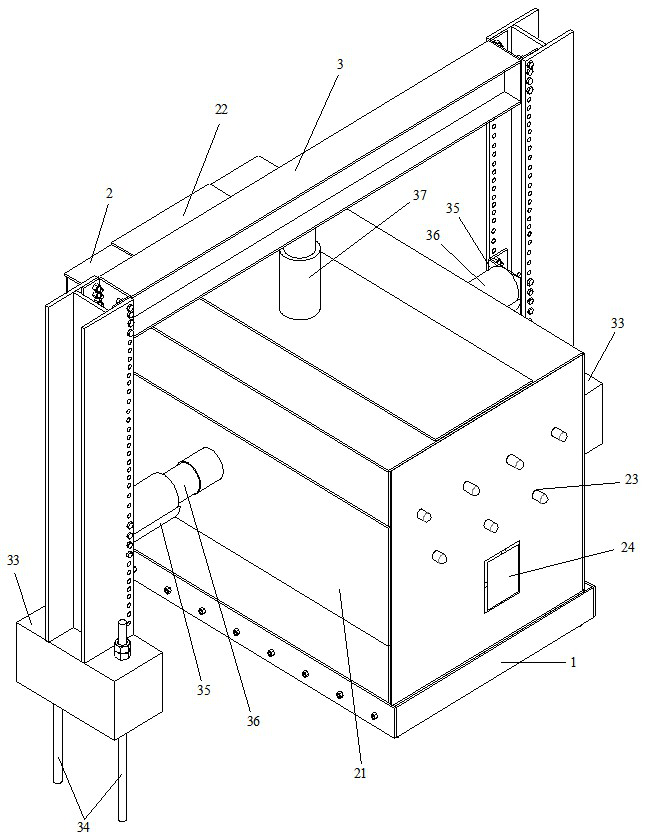
[0035] See figure 1 , a three-dimensional similar model device for visualizing internal cracks in rock mass, including a horizontally arranged rectangular base platform 1, a test box 2 and a loading portal 3, the test box 2 is arranged below the loading portal 3, and passes through the base platform 1 rolling arrangement on the experimental field;

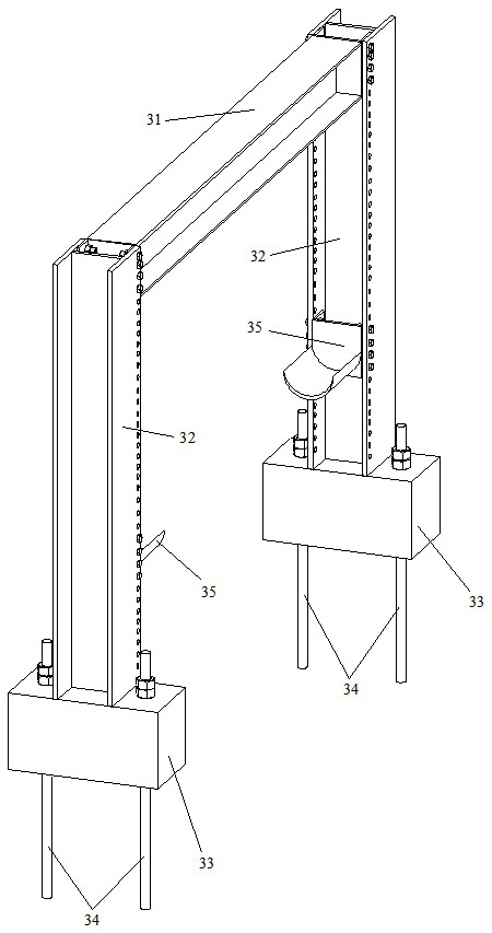
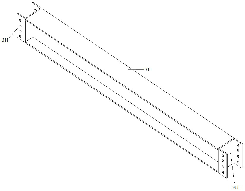
[0036] The loading mast 3 includes a horizontal top beam 31 and a pair of columns 32,

[0037] See figure 2 , each of the columns is an upright H-shaped steel, a pair of webs on a pair of H-shaped steels are arranged in parallel, the lower end of each column is fixed with a rectangular solid steel base 33, and each solid steel base 33 passes through a The high-strength screw mandrel 34 is fixedly installed on the experimental field;

[0038] A pair of groove seats 35 are correspondingly installed on the opposite sides of the pair of columns 32, and a pair of jacks 36 are correspondingly installed on the pair of groove seats 35,...


PUM


Abstract

The invention belongs to the technical field of underground stope simulation indoor tests, and particularly relates to a rock mass internal fracture visualization three-dimensional similar model device, which comprises a horizontally arranged rectangular base platform, a test box and a loading portal, the test box is internally compacted and filled with a simulation rock mass, and the test box isarranged below the loading portal, and is arranged on an experiment site in a rolling mode. The loading portal comprises a horizontal top cross beam and a pair of stand columns. A pair of groove seatsare correspondingly mounted on the opposite sides of the pair of stand columns, a pair of jacks are correspondingly mounted on the pair of groove seats, and a plunger at one end of each jack makes contact with the side face of the test box body; a plunger at one end of the third jack is in contact with the middle part of the lower end surface of the top cross beam; three or more rubber inflationcore mold holes which are formed in a staggered mode are horizontally formed in the upper portion of the test box body in a penetrating mode, and a rectangular stope excavation opening is formed in the lower portion of the test box body. The rock mass fracture development and evolution characteristics and the experimental process under the action of the external load can be visually displayed in real time.

Description

technical field [0001] It belongs to the technical field of underground stope simulation indoor test, and relates to a similar simulation test device for visualizing the dynamic expansion and evolution process of cracks in surrounding rocks in mine stopes or highway tunnels, specifically a three-dimensional similar model device for visualizing cracks inside rock mass . Background technique [0002] Similarity simulation is a science that studies similar phenomena in nature. It provides a similar judgment method and is used to guide the model test. Using the research results on the model, it can infer the mechanical phenomena that may occur in the prototype and the law of rock mass stress distribution, so as to solve practical problems in rock mass engineering production. [0003] In the indoor simulation test of underground engineering or tunnel engineering, there is a lack of similar simulation test devices for observing and collecting the dynamic expansion of internal cra...

Claims


Application Information

Patent Timeline
IPC IPC(8): G01N3/12G01N3/02
CPCG01N3/12G01N3/02
Inventor 袁海平熊礼军陈晨张羽俞祥杰叶晨旭
Owner HEFEI UNIV OF TECH
Learn More