
LED drive circuit for teaching

A technology of LED drive and LED circuit, which is applied in the direction of educational appliances, teaching models, electrical components, etc., can solve the problems of increasing teaching cost, over-integration, and high design cost, and achieve the effect of reducing teaching cost and exercising hands-on ability

Inactive Publication Date: 2021-01-12
YANCHENG INST OF TECH
View PDF0 Cites 0 Cited by
  • Summary
  • Abstract
  • Description
  • Claims
  • Application Information

AI Technical Summary

Problems solved by technology

[0002] With the development of science and technology, LED, as a new type of light source, has the advantages of small size, low power consumption, high light efficiency, long life, and environmental protection. It is widely used in the field of lighting, and various LEDs have emerged. Drive circuit, in order to obtain the best lighting effect, various LED drive circuits and LED drive chips have appeared on the market. In practical applications, the use of different LED drive circuits will have an impact on luminous efficiency and lifespan
[0003] In colleges and universities, when students design LED drive circuits, they often use LED drive chips to drive LEDs. However, the integration of LED drive chips is relatively complete. Finally, the driver chip needs to be replaced as a whole, which results in a relatively high design cost. In addition, the chips are packaged and too integrated, so the use of LED driver chips for students' circuit design learning can not exercise students' hands-on ability well, and on the other hand On the one hand, it also increases the cost of teaching

Method used


Image

  • LED drive circuit for teaching
  • LED drive circuit for teaching

Examples


Embodiment Construction

[0021] Below in conjunction with accompanying drawing and specific embodiment, further illustrate the present invention, should be understood that these examples are only for illustrating the present invention and are not intended to limit the scope of the present invention, after having read the present invention, those skilled in the art will understand various aspects of the present invention All modifications of the valence form fall within the scope defined by the appended claims of the present application.

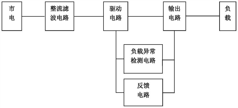
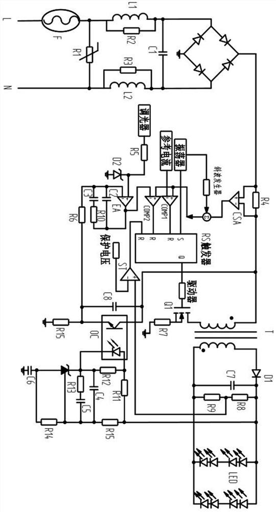
[0022] A teaching LED driving circuit, such as figure 1 , 2 As shown, it includes a rectification filter circuit, a drive circuit, a transformer T, an output circuit, a load LED circuit, a load abnormality detection circuit, and a feedback circuit, and is characterized in that: a rectification filter circuit, a drive circuit, a transformer T, an output circuit, and a load LED circuit in sequence One end of the abnormal load detection circuit is connected to the driv...


PUM


Abstract

The invention discloses an LED drive circuit for teaching, which comprises a rectification filter circuit, a drive circuit, a transformer T, an output circuit, a load LED circuit, a load abnormality detection circuit and a feedback circuit, wherein the rectification filter circuit, the drive circuit, the transformer T, the output circuit and the load LED circuit are connected in sequence; whereinthe load abnormality detection circuit and the feedback circuit are connected between the drive circuit and the output circuit, and the feedback circuit is a secondary winding feedback circuit. A driving chip is not needed, so that the circuit working principle can be clearly and visually understood, the device can be widely applied to electronic circuit teaching work of colleges and universities,the operational ability of students is exercised, and the teaching cost is reduced.

Description

technical field [0001] The invention relates to a control circuit, in particular to an LED driving circuit for teaching. Background technique [0002] With the development of science and technology, LED, as a new type of light source, has the advantages of small size, low power consumption, high light efficiency, long life, environmental protection, etc., and is widely used in the field of lighting, and various LEDs have appeared Drive circuit, in order to obtain the best lighting effect, various LED drive circuits and LED drive chips have appeared on the market. In practical applications, the use of different LED drive circuits will have an impact on luminous efficiency and life. [0003] In colleges and universities, when students design LED drive circuits, they often use LED drive chips to drive LEDs. However, the integration of LED drive chips is relatively complete. Finally, the driver chip needs to be replaced as a whole, which results in a relatively high design cost...

Claims


Application Information

Patent Timeline
IPC IPC(8): H05B45/30G09B23/18
CPCG09B23/183H05B45/30
Inventor 卞金洪王媛媛陈传杰方忠庆周锋
Owner YANCHENG INST OF TECH
Learn More