Supercharge Your Innovation With Domain-Expert AI Agents!

Wire coil clamping device and fishing reel winder

A clamping device and reel technology, which can be used in fishing reels, fishing, animal husbandry, etc. It can solve the problems of poor stability of the reel, troublesome operation, and inability to rewind the fishing line.

Pending Publication Date: 2021-01-15
王景海 +1
View PDF0 Cites 2 Cited by
  • Summary
  • Abstract
  • Description
  • Claims
  • Application Information

AI Technical Summary

Problems solved by technology

The above-mentioned wire reel clamping device, because the wire reel chuck is fixed on the wire reel locking arm, when in use, the center hole of the wire reel is in line contact with the wire reel chuck, and the wear and tear on the wire reel and the wire reel chuck Severe, loud noise; when using reels of different specifications, the reel chuck cannot be automatically positioned on the central axis of the reel, and repeated adjustments are required, which is cumbersome to operate, especially after long-term use causes certain wear on the reel chuck. When winding the line, the reel has poor stability and is easy to shake; the function is single, and the fishing line cannot be rewound
Existing fishing reel winders are only suitable for use with fishing rods, and the use environment is limited, so it is not suitable for separate winding for different fishing reels

Method used


Image

  • Wire coil clamping device and fishing reel winder
  • Wire coil clamping device and fishing reel winder
  • Wire coil clamping device and fishing reel winder

Examples


Embodiment Construction

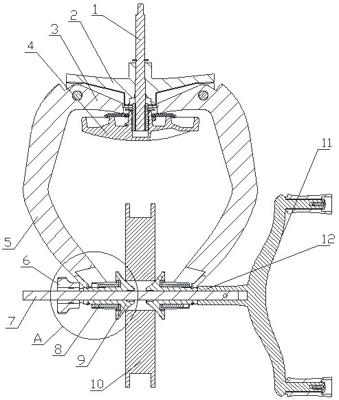
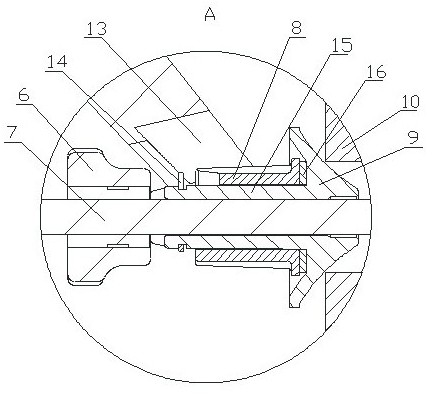
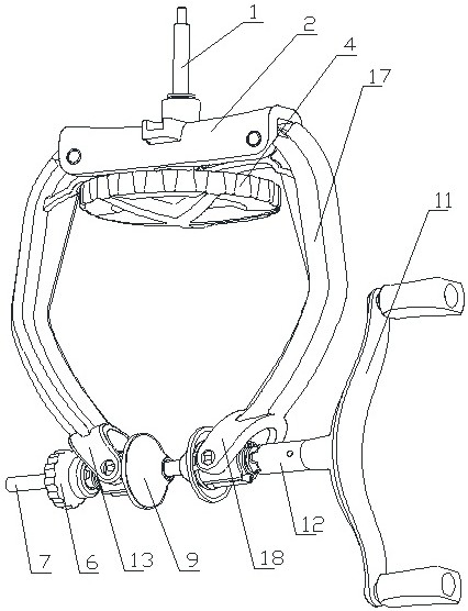
[0031] Such as Figure 1-Figure 4 The shown wire reel clamping device includes a rotating shaft 1, a support arm 2, a left wire reel clamping arm 5, a right wire reel clamping arm 17, a power arm 3, a lock nut and a lock disc 4, and the support arm 2 can be Freely rotatable is located on the rotating shaft 1, and the left wire reel clamping arm 5 and the right wire reel clamping arm 17 are respectively hinged on the two ends of support arm 2, from figure 1 , figure 2 It can be seen from the figure that the lower side of the support arm 2 is provided with a left and right connecting groove, so that the cross section of the support arm is U-shaped with the opening downward, and the upper ends of the left thread reel holding arm 5 and the right thread reel holding arm 17 are They are respectively hinged in the connection grooves at the left and right ends of the support arm. The hinge shafts where the left and right reel clamping arms are connected to the support arms are resp...


PUM


Abstract

The invention discloses a wire coil clamping device and a fishing reel winder and relates to the field of fishing tools. The wire coil clamping device comprises a left wire coil clamping arm and a right wire coil clamping arm. The lower ends of the left wire coil clamping arm and the right wire coil clamping arm are respectively provided with a left hinge seat and a right hinge seat, and a left clamping sliding sleeve and a right clamping sliding sleeve are respectively hinged in the left hinge seat and the right hinge seat. A left connecting shaft and a right connecting shaft are arranged inthe left clamping sliding sleeve and the right clamping sliding sleeve respectively, a right conical clamping head is arranged at the left end of the right connecting shaft, a left conical clamping head is arranged at the right end of the left connecting shaft, the right clamping sliding sleeve makes surface contact with the right conical clamping head, and the left clamping sliding sleeve makes surface contact with the left conical clamping head. A sliding sleeve limiting ring is arranged on the right connecting shaft, and a sliding sleeve limiting ring is arranged on the left connecting shaft. The fishing reel winder is provided with a telescopic rod and the wire coil clamping device. The wire coil clamping device and the fishing reel winder have the advantages of being simple in structure, convenient to use, not prone to damaging, long in service life, stable in use, low in noise and the like.

Description

technical field [0001] The invention relates to the field of fishing gear, in detail, it is a reel clamping device and fishing reel with simple structure, convenient use, not easy to damage, long service life, stable use, low noise, dual functions of winding and rewinding Winder. Background technique [0002] We know that in order to wind the fishing line on the fishing reel, technicians have developed a fishing reel winder. The structures of the existing fishing reel winders are various, but they all include a The wire reel clamping device and the connection seat used to connect with the fishing rod, the wire reel clamping device includes a left wire reel clamping arm and a right wire reel clamping arm to limit the clamping of the wire reel, the connection seat and the wire reel The clamping device is fixedly connected directly or fixedly connected via the support arm. When in use, the left wire reel clamping arm and the right wire reel clamping arm are clamped on both si...

Claims


Application Information

Patent Timeline
IPC IPC(8): A01K89/015A01K87/06
CPCA01K87/06A01K89/015
Inventor 张雪山王景海
Owner 王景海
Features
  • R&D
  • Intellectual Property
  • Life Sciences
  • Materials
  • Tech Scout
  • Unparalleled Data Quality
  • Higher Quality Content
  • 60% Fewer Hallucinations
Learn More