A kind of pneumatic endoscope bending body
An endoscope and bending technology, applied in the field of endoscope, can solve the problems of low maintenance efficiency, high cost, time delay, etc., and achieve the effects of large bending range, simple device and low cost
- Summary
- Abstract
- Description
- Claims
- Application Information
AI Technical Summary
Problems solved by technology
Method used
Image
Examples
Embodiment 1
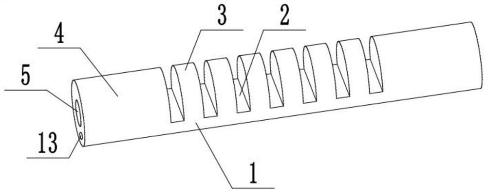
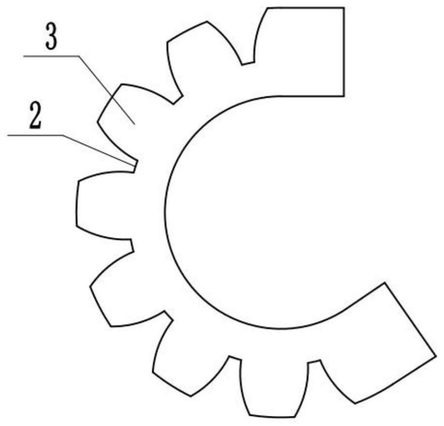
[0036] like Figure 1-Figure 3 As shown, this embodiment provides a pneumatic endoscope bending body, including a base body 1, the base body 1 is made of silica gel material, of course, it can also be made of other soft materials that can deform when the air pressure changes. Such as latex; substrate 1 has a slender profile, and one end of substrate 1 is provided with camera installation part 4, and camera installation part 4 is equidiametrically arranged with substrate 1, and camera installation part 4 inside has camera installation cavity 6, and camera installation cavity 6 is used for Enclose the camera module, and provide a camera hole 5 at the front end of the camera mounting part 4, the opening position of the camera hole 5 matches the lens position of the camera module; on the substrate 1, a number of axial intervals are arranged for making the substrate 1 Bent and deformed depressions 2, several depressions 2 are distributed on one side of the base 1 along a straight l...
Embodiment 2
[0043] like Figure 4-Figure 6 As shown, this embodiment provides a pneumatic endoscope bending body. On the basis of Embodiment 1, the pneumatic endoscope bending body of this embodiment also has the following characteristics:
[0044] Two rows of depressions 2 are evenly arranged along the circumference of the base body 1, and each row of air-filled cavities 7 is connected through an injection and suction channel 8, and the base body 1 between the injection and suction channels 8 forms a base 11, and a data line hole is arranged on the base 11 12 and functional channel 14, two injection and suction ports 9 are correspondingly arranged at one end of the base body 1, and there is a gap 15 between adjacent protruding parts 3 on the same cross section, so that when one side expands and the other side does not expand, no It will affect each other; the two injection and suction ports 9 are respectively connected to the injection and suction device, and the different injection and ...
Embodiment 3
[0047] like Figure 7-Figure 9 As shown, this embodiment provides a pneumatic endoscope bending body. On the basis of Embodiment 1, the pneumatic endoscope bending body of this embodiment also has the following characteristics:
[0048] The depressions 2 are evenly arranged in three rows along the circumference of the base body 1, and each row of air-filled chambers 7 is respectively connected through a suction channel 8, and the base body 1 between the injection and suction channels 8 forms a base 11, and a data line hole is arranged on the base 11 12 and functional channels 14, three injection and suction ports 9 are correspondingly arranged at one end of the base body 1, and there are gaps 15 between adjacent protruding parts 3 on the same cross section, so that when one side expands and the other side does not expand, no It will affect each other; the three injection and suction ports 9 are respectively connected to the injection and suction device, one or two injection an...
PUM
 Abstract
Description
Claims
Application Information
 - R&D
- Intellectual Property
- Life Sciences
- Materials
- Tech Scout
- Unparalleled Data Quality
- Higher Quality Content
- 60% Fewer Hallucinations
Browse by: Latest US Patents, China's latest patents, Technical Efficacy Thesaurus, Application Domain, Technology Topic, Popular Technical Reports.
© 2025 PatSnap. All rights reserved.Legal|Privacy policy|Modern Slavery Act Transparency Statement|Sitemap|About US| Contact US: help@patsnap.com


