Buffer type liftable machine tool for precision instrument machining

A technology of precision instruments and machine tools, used in metal processing mechanical parts, metal processing equipment, manufacturing tools, etc., can solve the problems of complex lifting structure, inconvenient maintenance and maintenance, etc.

Inactive Publication Date: 2021-01-15
李经缙
View PDF0 Cites 0 Cited by
  • Summary
  • Abstract
  • Description
  • Claims
  • Application Information

AI Technical Summary

Problems solved by technology

[0004] The object of the present invention is to provide a buffer type liftable machine tool for precision instrument processing, to solve the problem that the lifting machine tool in the prior art mentioned in the background art has a complicated lifting structure and is not easy to repair and maintain during the use process

Method used


Image

  • Buffer type liftable machine tool for precision instrument machining
  • Buffer type liftable machine tool for precision instrument machining
  • Buffer type liftable machine tool for precision instrument machining

Examples


Embodiment 1

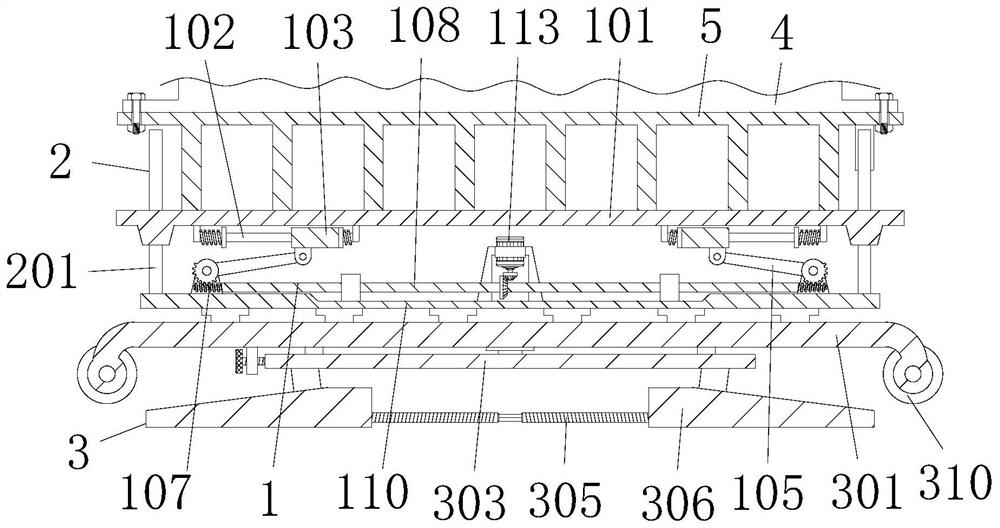
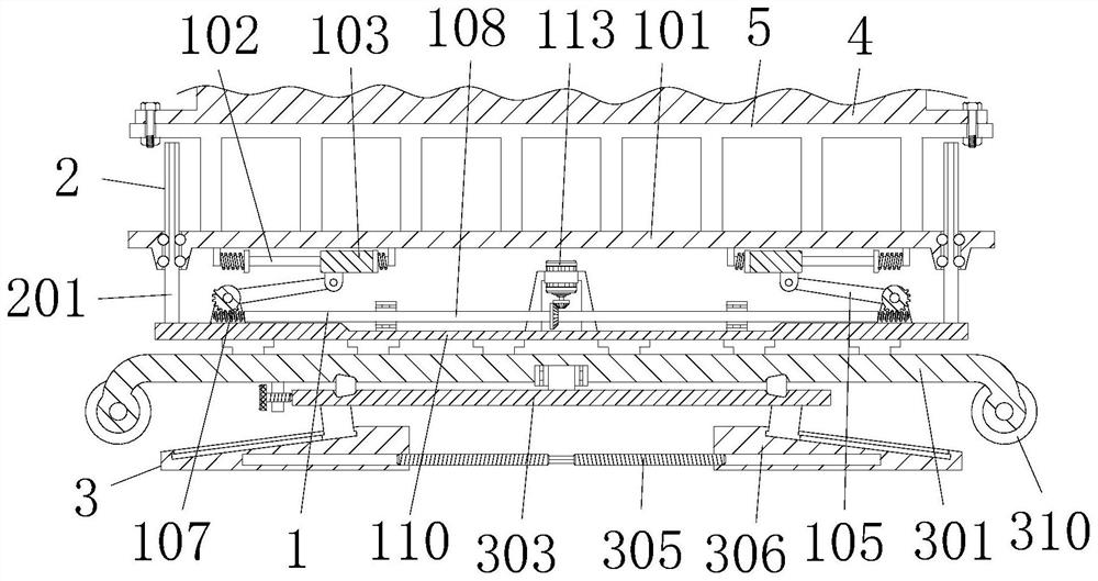
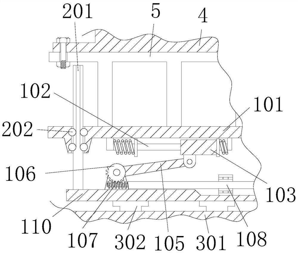
[0038] A buffer type liftable machine tool for precision instrument processing, including a machine tool 4. The machine tool 4 is a machine tool for precision instrument processing. The specific model is not limited, as long as it meets the needs of the operation. The bottom of the machine tool 4 is fixedly connected with a bracket 5, and the bracket 5 There is a lifting device 1 below, and the lifting device 1 includes a horizontal plate 101, a limit column 102, a first slider 103, a first support 104, a diagonal rod 105, a worm wheel 106, a worm 107, a long rod 108, and a second support. 109, top plate 110, the first bevel gear 111, the second bevel gear 112 and the servo motor 113, the bottom left and right sides of the horizontal plate 101 are all provided with the first slide block 113, and the first slide block 103 is movably sleeved at the limit On the positioning column 102, the two ends of the limiting column 102 are provided with a connecting plate 1022, the connectin...

Embodiment 2

[0041] As an option, see Figure 1-3 , a liftable machine tool for precision instrument processing, a limit device 2 is provided on the left and right sides of the horizontal plate 101, the limit device 2 includes a vertical rod 201 and a steel ball 202, the outer wall of the vertical rod 201 runs through the horizontal plate 101, and the outer wall of the vertical rod 201 The left and right sides are movably connected with steel balls 202 through grooves. The steel balls 202 reduce the friction between the vertical bar 201 and the horizontal plate 101. The outer wall of the steel ball 202 is matched with the inner wall groove of the horizontal plate 101. The bottom of the vertical bar 201 is in contact with the top plate. The tops of 110 are fastened together.

[0042] The solution in this embodiment can be selectively used in combination with the solutions in other embodiments.

Embodiment 3

[0044] As an option, see figure 1 , 2 , 3, 5 and 6, precision instrument processing with liftable machine tools, the bottom of the top plate 110 is provided with a support device 3, the support device 3 includes a square plate 301, a pole 302, a circular plate 303, a conical wheel 304, a double-ended stud 305, base 306, second slide block 307, bolt 308, riser 309 and roller 310, the top equidistant of square plate 301 is fixedly connected with strut 302, and strut 302 plays the role of support to opposite plate 301 and top plate 110, The top of the pole 302 is fixed together with the bottom of the top plate 110, the left and right ends of the bottom of the square plate 301 are rotatably connected with rollers 310, the rollers 310 facilitate the movement of the square plate 301, and the bottom of the square plate 301 is rotatably connected with a circular plate 303, the left and right sides of the top groove of the circular plate 303 are connected with conical wheels 304, the ...


PUM


Abstract

The invention discloses a buffer type liftable machine tool for precision instrument machining. The buffer type liftable machine tool comprises a machine tool body, and a support is fixedly connectedto the bottom of the machine tool body. According to the liftable machine tool for precision instrument machining, lifting of the machine tool is achieved, production and maintenance are convenient, the cost is low, vertical lifting of a transverse plate is guaranteed, uneven stress of a lifting device is avoided, the stability of the machine tool is guaranteed; through cooperation of a square plate, a circular plate, a double-end stud, a rolling wheel, a conical wheel, a second sliding block and a base, the liftable machine tool for precision instrument machining is convenient to move, aftermovement, supporting can be carried out on the liftable machine tool for precision instrument machining, the stability of the liftable machine tool for precision instrument machining is guaranteed; and through cooperation of the circular plate, a bolt and an ejection plate, the angle of the machine tool is convenient to rotate and fix, the operation process is simple, and the liftable machine toolfor precision instrument machining can better meet the use requirements of people, and is suitable for popularization and use.

Description

technical field [0001] The invention relates to the technical field of machine tools, in particular to a buffer type liftable machine tool for precision instrument processing. Background technique [0002] With the continuous improvement of science and technology, all kinds of machine tools have gradually emerged. At this stage, they have become indispensable processing tools in the field of mechanical processing. Especially when processing precision instruments, operators need to perform frequent operations. In order to facilitate the operation of operators , a lift machine tool has been proposed in the prior art. [0003] However, in the process of using the lifting machine tool in the prior art, the lifting structure is complicated, which is not convenient for repair and maintenance, and there is no auxiliary support during the working process of the lifting structure, so the lifting structure itself is easily displaced by force, resulting in the instability of the machin...

Claims


Application Information

Patent Timeline
IPC IPC(8): B23Q1/00B23Q1/01B23Q11/00
CPCB23Q1/00B23Q1/01B23Q11/00B23Q11/0032
Inventor 李经缙
Owner 李经缙
Why Eureka
Try Eureka