Slide rail capable of enhancing rigidity modulus

A technology of rigidity modulus and slide rail, which is applied in the special position of the vehicle, vehicle seat, movable seat, etc., can solve problems such as stiffness reduction, noise, and distress, and achieve the effect of improving the mode

Active Publication Date: 2021-01-15
KEIPER (CHANGSHU) SEATING MECHANISMS CO LTD
View PDF9 Cites 5 Cited by
  • Summary
  • Abstract
  • Description
  • Claims
  • Application Information

AI Technical Summary

Problems solved by technology

Since the center of gravity of the normal seat load is at the rear position, the suspension of this upper rail will affect the overall rigidity of the slide rail, and it is easier to vibrate when the vehicle is running, resulting in poor body feeling and even some noise.
[0004] In some models, in order to facilitate the third row of passengers to enter the car, and due to the space constraints of the rear seats, the second row of slide rails can only use a shorter cage, so its rigidity is not very ideal
[0005] In addition, a development trend of slide rails is light weight. With the application of high-strength steel, slide rails have been able to overcome strength problems, making them thinner and lighter, but the ensuing decrease in stiffness also gives Industry products bring difficulties, which limits its further lightweight

Method used


Image

  • Slide rail capable of enhancing rigidity modulus
  • Slide rail capable of enhancing rigidity modulus
  • Slide rail capable of enhancing rigidity modulus

Examples


Embodiment 1

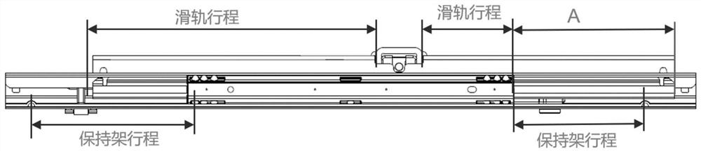
[0043] For the front seat of the car, generally the slide rail and the slide rail stroke are longer, so a longer cage 30 can be matched. Due to the limitation of the length of the upper slide rail, the length of the cage 30 will be limited within a certain range; when the long cage 30 is used, the modal performance of the front end of the slide rail is generally good, but the middle and rear sections of the slide rail do not have the cage 30 Braces, sometimes have issues with poor modality. If the mode is not up to standard, it will cause the parts to resonate, which will lead to problems such as abnormal sound and reduced durability.

[0044] Based on the above reasons, this embodiment designs a sliding cage 30 based on the cage 30 of the front row seat slide rail, and the second half lengthens the sliding cage 30; The rear section provides additional support for the upper rail, especially in vibration situations, which can effectively improve the mode of the slide rail and ...

Embodiment 2

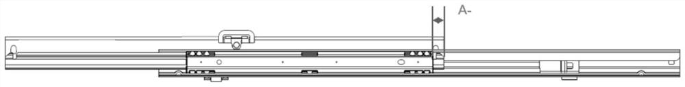
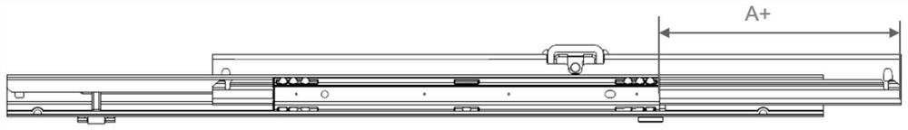
[0058] This embodiment is aimed at the optimization of the slide rails of the short cages 30 in the rear row. The rear stroke of the slide rails in the rear seats of the car is generally short, so the selected cage 30 is relatively short; When the rail is at the design position or the front position of the comfortable stroke, the slide rail will have a problem of poor mode. The root cause is that the rear end of the upper slide rail is in a suspended state and lacks support. The present invention designs an auxiliary support structure used in conjunction with the short cage 30, through the cooperation of the short cage 30 and the new structure, it can always provide support for the upper rail, especially in the case of vibration, which can effectively improve the mode of the slide rail performance. The specific plan is as follows:

[0059] A slide rail with enhanced rigidity modulus, the slide rail is composed of an upper rail assembly 10, a lower rail assembly 20 and a cage ...


PUM


Abstract

The invention relates to an automobile seat sliding rail, in particular to a sliding rail capable of enhancing rigidity modulus. The sliding rail is composed of an upper rail assembly, a lower rail assembly and retainers; the upper rail assembly is slidably arranged in a sliding groove of the lower rail assembly through a pair of retainers, and first protruding ribs and / or steel ball clamping grooves are arranged on the surfaces, in contact with the upper rail assembly and the lower rail assembly, of the retainers at intervals. Steel balls are installed in the steel ball clamping grooves, supporting structures extending backwards in the field length direction of the retainers are arranged at the rear ends of the retainers; and when the upper rail assembly slides backwards to the farthest stroke, the supporting structure provides longitudinal auxiliary supporting for the middle rear section of the upper rail assembly, and the supporting structure makes contact with the lower rail assembly, and a gap is reserved between the supporting structure and the upper rail assembly. The whole upper rail can be supported through the supporting structures, and the mode of the sliding rail can beeffectively improved especially under the working condition of jolting and vibrating, so that the overall rigidity of the sliding rail is improved, and noise generated by the sliding rail in an automobile can be reduced.

Description

technical field [0001] The invention relates to the improvement of automobile slide rail components, in particular to a slide rail with enhanced rigidity modulus. Background technique [0002] In order to meet the requirements of passenger comfort, car seats usually need to implement angle adjustment and displacement adjustment, and recliners are generally used for adjustment; displacement adjustment is realized by setting the seat on the slide rail, and there is a liner between the seat and the slide rail Balls are used to reduce friction, and the balls are all set in the cage to prevent scattering. [0003] Such as Figure 1-3 Shown is the sliding state diagram of the existing car seat slide rail assembly: the movement mode of the cage is rolling; the operation mode of the slide rail is sliding, and the movement stroke of the cage is half of the movement stroke of the slide rail. At this time, because the distance between the rear end of the upper rail and the rear end of...

Claims


Application Information

Patent Timeline
Patent Type & Authority Applications(China)
IPC IPC(8): B60N2/07
CPCB60N2/0722B60N2/0705B60N2/0727B60N2/073
Inventor 胡海拉黄彬付文金倪洪斌刘东
Owner KEIPER (CHANGSHU) SEATING MECHANISMS CO LTD
Why Eureka
Try Eureka