
Locking device for battery restraining tray

A locking device and restraint technology, which is applied in the field of battery restraint tray locking devices, can solve the problems of battery overvoltage, uneven control, low voltage, etc., and achieve the effect of improving production efficiency and facilitating production automation

Pending Publication Date: 2021-01-15
ZHEJIANG HANGKE TECH
View PDF0 Cites 0 Cited by
  • Summary
  • Abstract
  • Description
  • Claims
  • Application Information

AI Technical Summary

Problems solved by technology

Therefore, in the test process, in order to ensure the consistency of the battery dimensions, it is necessary to use a restraint tray to compress the battery and give a given pressure. At present, the cylinder is directly compressed and opened, and the control of the force is uneven and cannot be fed back. The size of the force and the stroke control of the expansion and contraction are easy to overvoltage or undervoltage on the battery, etc.

Method used


Image

  • Locking device for battery restraining tray
  • Locking device for battery restraining tray
  • Locking device for battery restraining tray

Examples


Embodiment 1

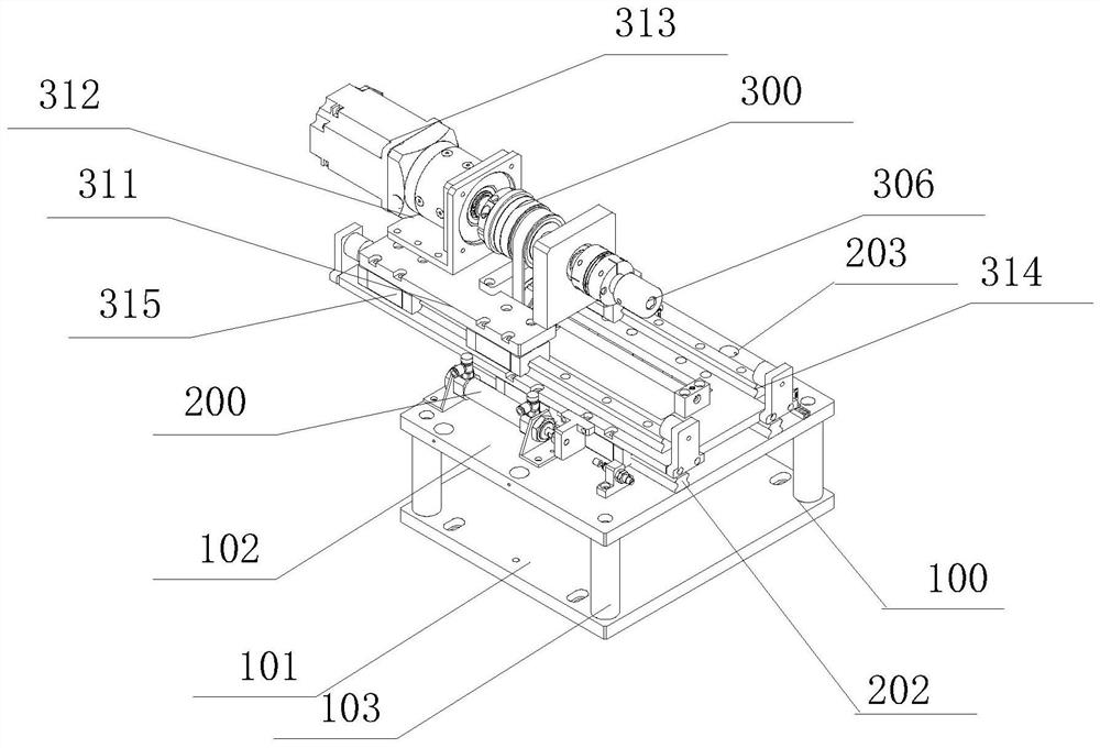
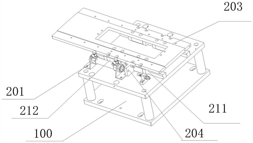
[0020] Embodiment 1 A battery restraint tray locking device according to the present invention includes:

[0021] The base 100 is provided with a mounting platform on the top for supporting and installing the front and rear drive mechanisms;

[0022] The front and rear driving mechanism 200 is arranged on the base 100 and includes a driving device 201, a fixed rail slider assembly 202 and a slider fixing plate 203. The driving device 201 is fixed on the installation platform at the top of the base 100, and its pushing end It is connected with the fixed guide rail slider assembly to provide driving force; the fixed guide rail slider assembly 202 is laid on the installation platform of the base 100 along the driving direction of the driving device, and a slider fixing plate 203 is fixed on the sliding part for use Drive the slider fixing plate 203 to slide; the slider fixing plate 203 is arranged beside the driving device 201, and is connected with the pushing end of the driving...

Embodiment 2

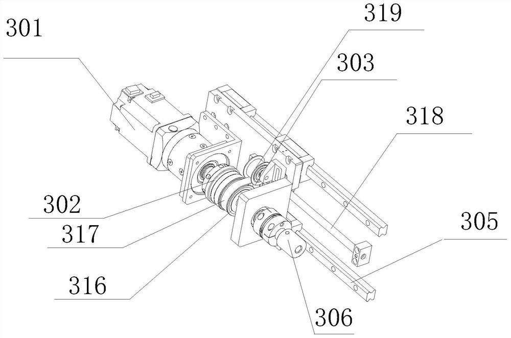
[0030] Embodiment 2 A battery restraint tray locking device according to the present invention includes a base, a front and rear drive mechanism and a synchronous movement mechanism. The front and rear driving mechanism includes a driving device, a fixed guide rail slider assembly and a slider fixing plate, which are arranged on the base. The synchronous motion mechanism is arranged on the slider fixing plate of the front and rear drive mechanism, and the synchronous motion mechanism is composed of a motor drive device, a torque limiting device, a screw drive device, a synchronous pulley drive device and a moving guide rail slider device composition.

[0031] The battery restraint tray locking device provided by the present invention pushes the synchronous movement mechanism through the front and rear drive mechanism, so that the sleeve head on the synchronous movement mechanism docks with the head of the lead screw on the battery restraint tray. The motor drive unit of the s...


PUM


Abstract

A locking device for a battery restraining tray comprises a base, a front-back driving device, and a synchronous movement mechanism, wherein the top of the base is provided with a mounting platform; the front-back driving mechanism is arranged on the base, and comprises a driving device, a fixed guide rail sliding block assembly, and a sliding block fixing plate; a pushing end of the driving device is connected with the fixed guide rail sliding block assembly; a sliding part of the fixed guide rail sliding block assembly is fixedly provided with the sliding block fixing plate; the sliding block fixing plate is connected with the pushing end of the driving device by a connecting piece; the synchronous movement mechanism is arranged on the front-back driving mechanism, and comprises a motordriving device, a torque limiting device, a lead screw transmission device, a synchronous pulley transmission device, and a movable guide rail sliding block device; the motor driving device is mountedon the sliding block fixing plate in a sliding manner by the movable guide rail sliding block device; a sleeve head is assembled at an end of an output shaft of the torque limiting device; and the screw rod transmission device is in belt connection with the output shaft of the torque limiting device by the synchronous pulley transmission device. The locking device has the beneficial effects of improving production efficiency, pipelining a product, and facilitating production automation.

Description

technical field [0001] The invention relates to a battery restraint tray locking device, which belongs to the technical field of battery composition capacity testing. Background technique [0002] In the automatic production process of lithium batteries, especially in the process of forming and sizing, the shape of the battery cell will bulge due to the formation of gas, which directly affects the appearance quality of the battery cell. Therefore, in the test process, in order to ensure the consistency of the battery dimensions, it is necessary to use a restraint tray to compress the battery and give a given pressure. At present, the cylinder is directly compressed and opened, and the control of the force is uneven and cannot be fed back. The size of the force and the stroke control of the expansion and contraction are easy to overvoltage or undervoltage on the battery. Contents of the invention [0003] The purpose of the present invention is to provide a simpler and mor...

Claims


Application Information

Patent Timeline
Patent Type & Authority Applications(China)
IPC IPC(8): B65G47/74
CPCB65G47/74
Inventor 曹骥曹政郭凯华刘伟李求奖
Owner ZHEJIANG HANGKE TECH
Learn More