Stay cable combined vibration reduction device and method

A technology of vibration damping device and stay cable, which is applied in the erection/assembly of bridges, bridge parts, bridges, etc., can solve the problems of high installation position of dampers, affecting vibration damping effect, and inability to effectively exert vibration damping function, etc. Vibration reduction and easy installation

Active Publication Date: 2021-01-15
CHINA RAILWAY MAJOR BRIDGE ENG GRP CO LTD +1
View PDF18 Cites 3 Cited by
  • Summary
  • Abstract
  • Description
  • Claims
  • Application Information

AI Technical Summary

Problems solved by technology

[0004] Aiming at the defects existing in the prior art, the object of the present invention is to provide a cable-stayed combined damping device and method, which can solve the problem that the installation position of the damper required by the external damper in the prior art is relatively high, resulting in external The installation position of the built-in damper is the vibration stagnation point, which cannot effectively perform the vibration reduction function; at the same time, it solves the problem that the high-frequency vibration of the cable stay causes damage to the external damper of the cable stay and affects the vibration reduction effect

Method used


Image

  • Stay cable combined vibration reduction device and method
  • Stay cable combined vibration reduction device and method

Examples


Embodiment Construction

[0040]In order to make the purpose, technical solutions and advantages of the embodiments of this application clearer, the technical solutions in the embodiments of this application will be described clearly and completely in conjunction with the drawings in the embodiments of this application. Obviously, the described embodiments These are a part of the embodiments of this application, but not all of the embodiments. Based on the embodiments in this application, all other embodiments obtained by those of ordinary skill in the art without creative work shall fall within the protection scope of this application.

[0041]The embodiments of the present invention will be described in further detail below with reference to the accompanying drawings.

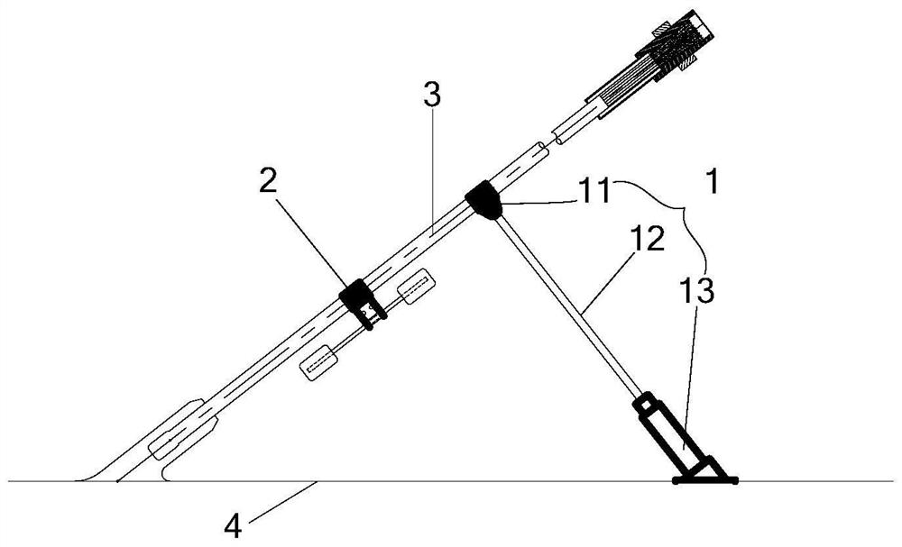
[0042]figure 1 It is a schematic structural diagram of a stay-cable combined vibration damping device in an embodiment of the present invention;figure 1 As shown, the present invention provides a stay cable combination damping device, including: ...


PUM


Abstract

The invention relates to the technical field of structural vibration control, in particular to a stay cable combined vibration reduction device and method; and the method comprises the following steps: determining the vibration fundamental frequency of a stay cable according to the parameters of the stay cable; determining the installation position of the external damper according to the vibrationreduction requirement of the stay cable; according to the stay cable fundamental frequency and the installation position of the external damper, determining the stay cable vibration standing point frequency at the installation position; determining the control frequency of a tuned mass damper to be installed according to the stay cable vibration standing point frequency at the installation position of the stay cable external damper; and installing the external damper according to the installation position of the external damper, and installing the tuned mass damper on the stay cable between the anchoring point and the external damper. The problems that in the prior art, an external damper is installed at a vibration stationary point, the vibration frequency adjacent to the vibration frequency corresponding to the stationary point cannot be brought into play for effective vibration reduction, and the stay cable external damper is poor in stay cable high-frequency vibration control effect can be solved.

Description

Technical field[0001]The invention relates to the technical field of structural vibration control, in particular to a stay-cable combined vibration damping device and method.Background technique[0002]With the development of science and technology and the research and development of new materials and technologies, the span of cable-stayed bridges has been continuously broken, and the number of cable-stayed bridges with a main span of more than 1,000m is also increasing. This has also led to the increasing use of extra-long stay cables (the "External Viscous Damper for Stay Cables" JT / T 1038-2016 stipulates that stay cables longer than 450m are extra-long stay cables). For longer stay cables, the flexibility of overlong stay cables will increase and the damping will be greatly reduced. Therefore, different types of vibrations are more likely to occur under the excitation of dynamic loads. A large number of engineering examples show that super-long stay cables are prone to fatigue fail...

Claims


Application Information

Patent Timeline
Patent Type & Authority Applications(China)
IPC IPC(8): E01D19/00E01D19/02E01D21/00E01D19/14
CPCE01D19/00E01D19/02E01D21/00E01D19/14
Inventor 吴肖波盛能军王泽豪赵海威汪正兴荆国强王波王翔马长飞刘鹏飞李东超
Owner CHINA RAILWAY MAJOR BRIDGE ENG GRP CO LTD
Why Eureka
Try Eureka