Throwing type net-shaped electric shock device

An electric shocker and mesh technology, which is applied in the field of throwing mesh electric shockers, can solve the problems of easy deviation, loss of resistance, and the effect of electric shock on objects that cannot be captured, and achieves the effect of large opening area.

Pending Publication Date: 2021-01-15
李社军
View PDF0 Cites 2 Cited by
  • Summary
  • Abstract
  • Description
  • Claims
  • Application Information

AI Technical Summary

Problems solved by technology

[0002] At present, when the army, armed police, and special police perform tasks such as arresting criminals or suspects, the traditional double electric shock needle electric shock device and single electric shock device often easily deviate from the arrested object during the arrest process, and cannot be effective. Therefore, there is an urgent need for a non-lethal capture weapon that can exert electric shock in time without precise aiming, so that the captured object can immediately lose its ability to resist. The ability to resist

Method used


Image

  • Throwing type net-shaped electric shock device
  • Throwing type net-shaped electric shock device
  • Throwing type net-shaped electric shock device

Examples


Embodiment 1

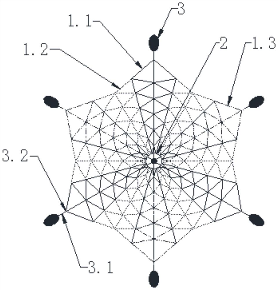
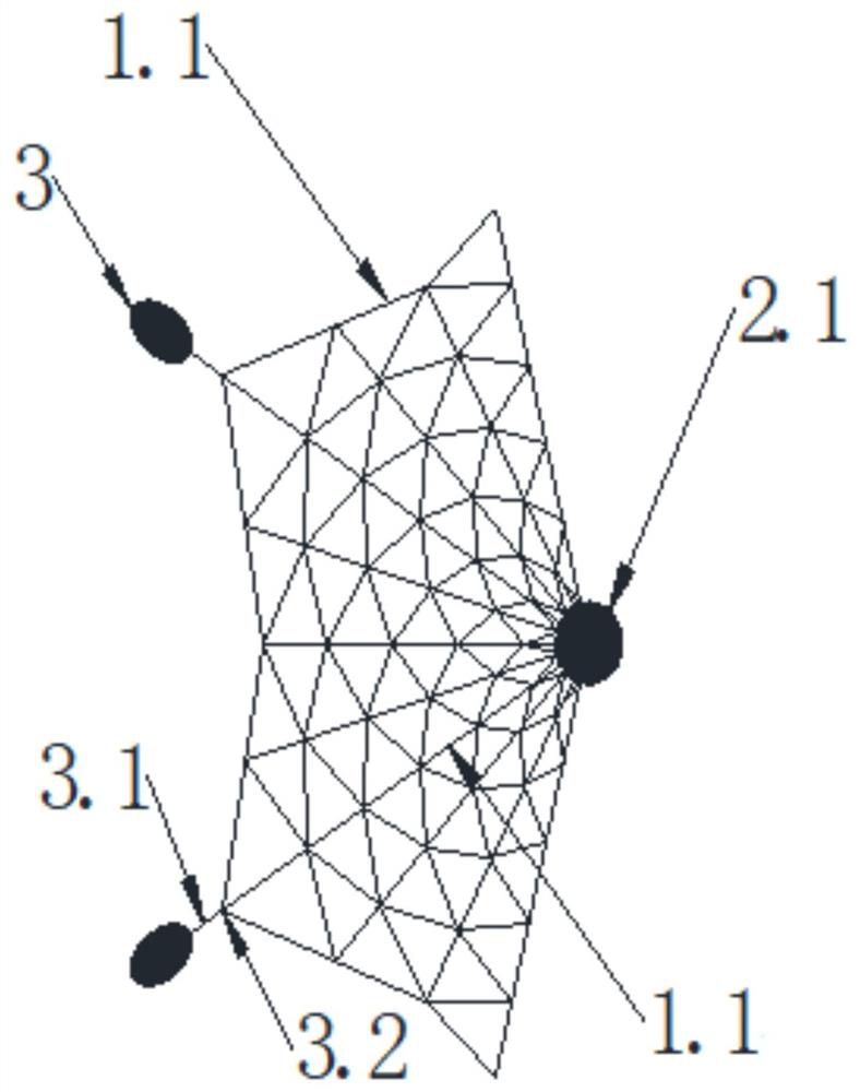
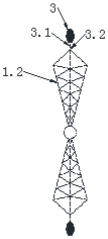
[0069] figure 1 It is a schematic structural diagram of the throwing mesh electric shocker of the present invention. Figure 2a-Figure 2d Schematic diagrams of the structures of the high-potential conductive grid, the insulating grid, the low-potential conductive grid and the mesh electric shocker in Embodiment 1 of the present invention are shown respectively. Figure 7 It is a structural schematic diagram of the high potential output end of the electric shock high voltage generator of the throwing mesh electric shock device of the present invention. Figure 8 It is a structural schematic diagram of the bottom potential output end of the electric shock high voltage generator of the throwing mesh electric shock device of the present invention. Figure 9 It is a side view of the shock high voltage generator of the throwing mesh electric shocker of the present invention. Figure 10 It is a schematic diagram of the connection state of the electric shock high voltage generator a...

Embodiment 2

[0081] figure 1 It is a schematic structural diagram of the throwing mesh electric shocker of the present invention. Figure 3a-Figure 3d Schematic diagrams of the structures of the high-potential conductive grid, the insulating grid, the low-potential conductive grid and the mesh electric shocker in Embodiment 1 of the present invention are shown respectively. Figure 7 It is a structural schematic diagram of the high potential output end of the electric shock high voltage generator of the throwing mesh electric shock device of the present invention. Figure 8 It is a structural schematic diagram of the bottom potential output end of the electric shock high voltage generator of the throwing mesh electric shock device of the present invention. Figure 9 It is a side view of the shock high voltage generator of the throwing mesh electric shocker of the present invention. Figure 10 It is a schematic diagram of the connection state of the electric shock high voltage generator a...

Embodiment 3

[0093] figure 1 It is a schematic structural diagram of the throwing mesh electric shocker of the present invention. Figure 4a-Figure 4d Schematic diagrams of the structures of the high-potential conductive grid, the insulating grid, the low-potential conductive grid and the mesh electric shocker of Embodiment 3 of the present invention are shown respectively. Figure 7 It is a structural schematic diagram of the high potential output end of the electric shock high voltage generator of the throwing mesh electric shock device of the present invention. Figure 8 It is a structural schematic diagram of the bottom potential output end of the electric shock high voltage generator of the throwing mesh electric shock device of the present invention. Figure 9 It is a side view of the shock high voltage generator of the throwing mesh electric shocker of the present invention. Figure 10 It is a schematic diagram of the connection state of the electric shock high voltage generator a...


PUM


Abstract

The embodiment of the invention discloses a throwing type net-shaped electric shock device. The throwing type net-shaped electric shock device comprises an electric shock high-voltage generator, a net-shaped electric shock device connected to the electric shock high-voltage generator, and net-shaped electric shock device transmitting tractors connected to the net-shaped electric shock device; wherein the net-shaped electric shock device comprises a high-potential conductive net, an insulating net and a low-potential conductive net, the high-potential conductive net is connected to the low-potential conductive net through the insulating net, and thus, the net-shaped electric shock device is in a cobweb shape; and the net-shaped electric shock device emitting tractors are arranged on the peripheral edge of the cobweb shape and each net-shaped electric shock device emitting tractor comprise a traction rope and a tractor body, one end of the traction rope is connected to the tractor body,and the other end of the traction rope is connected to the net-shaped electric shock device. The throwing type net-shaped electric shock device does not need accurate aiming and can give play to the electric shock effect in time, so that a captured object immediately loses the resistance capacity and is captured.

Description

technical field [0001] The invention relates to the field of security, in particular to a throwing type mesh electric shocker. Background technique [0002] At present, when the army, armed police, and special police perform tasks such as arresting criminals or suspects, the traditional double electric shock needle electric shock device and single electric shock device often easily deviate from the arrested object during the arrest process, and cannot be effective. Therefore, there is an urgent need for a non-lethal capture weapon that can exert electric shock in time without precise aiming, so that the captured object can immediately lose its ability to resist. The ability to resist, catch without a fight. At the same time, it is a capture device that reduces the casualties of law enforcement officers. [0003] The information disclosed in the background of the present invention is only intended to deepen the understanding of the general background of the present inventio...

Claims


Application Information

Patent Timeline
Patent Type & Authority Applications(China)
IPC IPC(8): F41H13/00
CPCF41H13/0018
Inventor 李社军李彦良
Owner 李社军
Why Eureka
Try Eureka