Image moire elimination method and device and LED display screen correction method

An LED display, moiré technology, applied in static indicators, instruments, etc., can solve problems such as affecting the correction effect of LED display

Active Publication Date: 2021-01-15
SHENZHEN LIDING PHOTOELECTRIC TECH
View PDF13 Cites 2 Cited by
  • Summary
  • Abstract
  • Description
  • Claims
  • Application Information

AI Technical Summary

Problems solved by technology

[0002] LED display is a kind of flat-panel display, which is widely used in many aspects, such as outdoor advertising, shopping malls, etc. Before using the LED display, it is necessary to calibrate the LED display to ensure the display effect. The current calibration method The corrected image is mainly obtained by shooting the LED display screen with a camera and other instruments, and the point-by-point correction is realized based on the corrected image. However, at present, most of the corrected images obtained by shooting the LED display screen with a camera and other instruments have moiré, and the moiré is a part of the beat-beating principle. This kind of performance, if the spatial frequency of the CCD / CMOS pixel of the photosensitive element of the camera is close to the spatial frequency of the image stripes displayed on the LED display screen, moiré will be affected by the interference of moiré. When the correction method is to use the correction method with moiré When the image is corrected for the LED display, it will directly affect the correction effect of the LED display

Method used


Image

  • Image moire elimination method and device and LED display screen correction method
  • Image moire elimination method and device and LED display screen correction method
  • Image moire elimination method and device and LED display screen correction method

Examples


Embodiment Construction

[0022] The technical solutions in the embodiments of the present invention will be clearly and completely described below in conjunction with the drawings in the present invention. Apparently, the described embodiments are only some of the embodiments of the present invention, not all of them. Based on the embodiments of the present invention, all other embodiments obtained by persons of ordinary skill in the art without making creative efforts belong to the protection scope of the present invention.

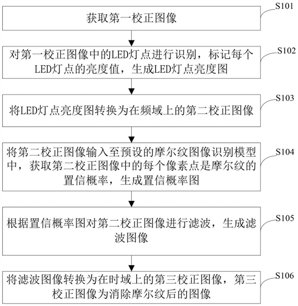
[0023] In one embodiment of the present invention, a method for eliminating image moiré is provided, such as figure 1 Shown, the elimination method of image moiré comprises the following steps:

[0024] Step S101: Acquire a first corrected image.

[0025] The first corrected image is an image captured by a camera after the LED display is turned on, and the first corrected image is an image formed in the time domain. Specifically, the camera may be a single-lens reflex camera o...


PUM


Abstract

The invention provides an image moire elimination method and device and an LED display screen correction method. The image moire elimination method comprises the steps of acquiring a first correctionimage; generating an LED lamp point brightness graph according to the first correction image; converting the LED lamp point brightness map into a second correction image in the frequency domain; inputting the second correction image into a preset moire image recognition model, obtaining a confidence probability that each pixel point in the second correction image is a moire, and generating a confidence probability graph; filtering the second corrected image according to the confidence probability graph to generate a filtered image; and converting the filtered image into a third corrected imagein the time domain. According to the method, the moire in the image can be effectively recognized and eliminated, the moire in an LED correction image is eliminated before an LED display screen is corrected, when the LED correction image is used for correction subsequently, interference of the moire is avoided, the display effect after correction is optimized, and the problem that the brightnessof the LED display screen is uneven due to the moire is effectively solved.

Description

technical field [0001] The invention relates to the field of LED display screen correction, in particular to an image moiré elimination method, device and LED display screen correction method. Background technique [0002] LED display is a kind of flat-panel display, which is widely used in many aspects, such as outdoor advertising, shopping malls, etc. Before using the LED display, it is necessary to calibrate the LED display to ensure the display effect. The current calibration method The corrected image is mainly obtained by shooting the LED display screen with a camera and other instruments, and the point-by-point correction is realized based on the corrected image. However, at present, most of the corrected images obtained by shooting the LED display screen with a camera and other instruments have moiré, and the moiré is a part of the beat-beating principle. This kind of performance, if the spatial frequency of the CCD / CMOS pixel of the photosensitive element of the cam...

Claims


Application Information

Patent Timeline
Patent Type & Authority Applications(China)
IPC IPC(8): G09G3/32
CPCG09G3/32G09G2320/0233
Inventor 何志民
Owner SHENZHEN LIDING PHOTOELECTRIC TECH
Why Eureka
Try Eureka