Light guide device, light source assembly and projection device

A technology of light guide device and light source assembly, applied in the direction of light guide, projection device, optical element, etc., can solve the problems of reducing output light brightness, reducing output light brightness, large light energy loss, etc.

Inactive Publication Date: 2014-01-22
QISDA OPTRONICS (SUZHOU) CO LTD +1
View PDF2 Cites 2 Cited by
  • Summary
  • Abstract
  • Description
  • Claims
  • Application Information

AI Technical Summary

Problems solved by technology

In fact, although the scheme of extending the length of the light guide device obtains better brightness uniformity by reflecting light more times, the light energy will cause a large loss in each reflection, and then after extend...

Method used


Image

  • Light guide device, light source assembly and projection device
  • Light guide device, light source assembly and projection device
  • Light guide device, light source assembly and projection device

Examples


Embodiment 1

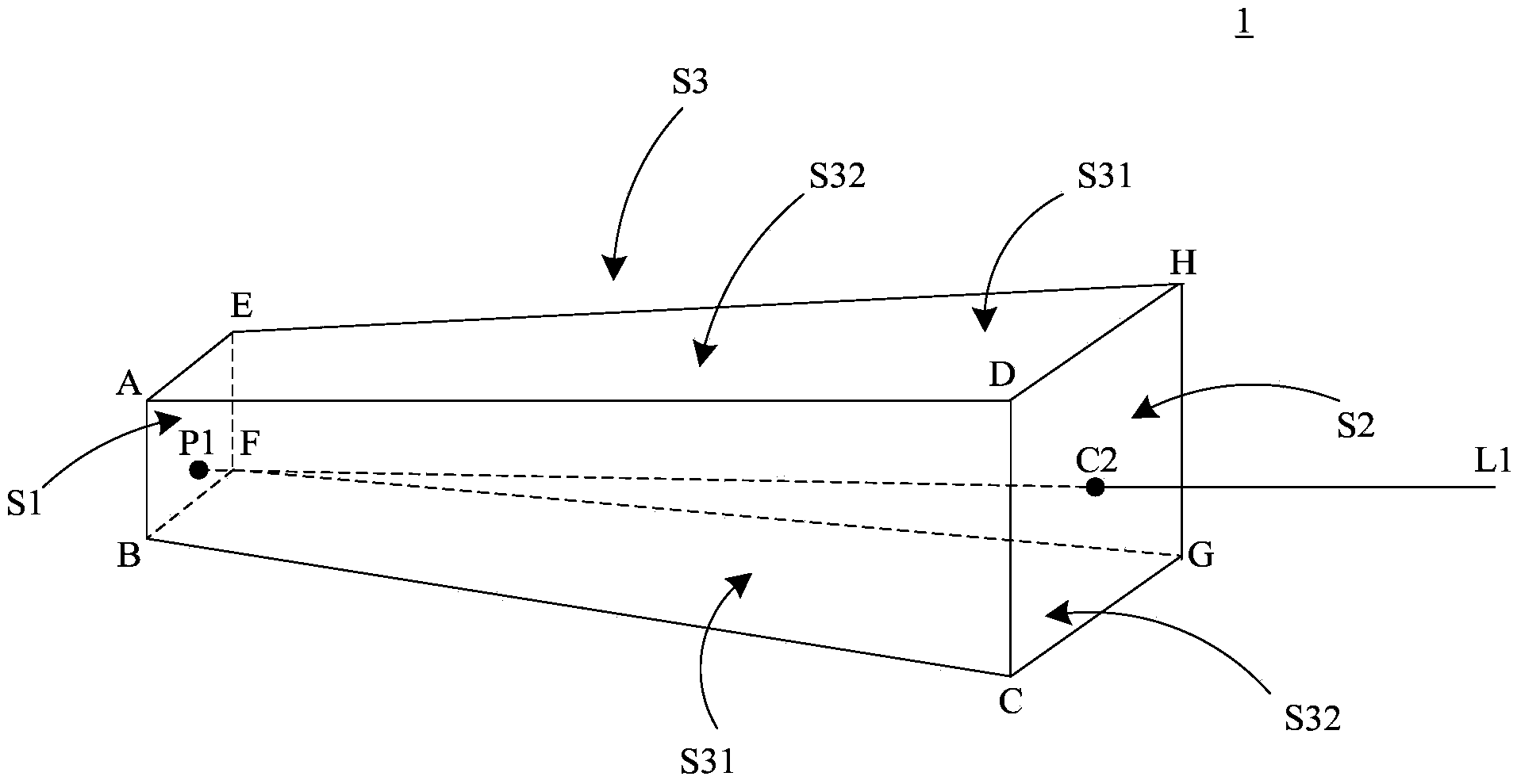
[0028] image 3 A schematic structural view of a light guide device provided by an embodiment of the present invention is shown, as shown in image 3 As shown, the light guide device in the embodiment extends along a straight line. The light guide device 1 has a light incident surface S1 (defined by the vertex ABFE) and a light exit surface S2 (defined by the vertex DCGH), and the light exit surface S2 is located opposite to the light incident surface S1 . In the center C2 of the light-emitting surface S2, a first central axis L1 perpendicular to the light-emitting surface S2 is defined. The intersection point of the first central axis L1 and the light-incident surface S1 is P1, which is not at the center of the light-incidence surface S1, that is, the first A central axis L1 does not pass through the center of the light incident surface S1.

[0029] In addition, the side wall S3 of the light guide device 1 connects the light incident surface S1 and the light exit surface S2...

Embodiment 2

[0038] Figure 5 It shows a schematic structural diagram of another light guide device provided by the embodiment of the present invention, such as Figure 5As shown, the light guide device 1' in this embodiment extends along a straight line, and the light guide device 1' has a light incident surface S1' and a surface S2'. The photoconductive device in this embodiment and image 3 The difference of the light guide device shown in is that: in this embodiment, the light incident surface S1' and the light exit surface S2' of the light guide device 1' are both circular.


PUM


Abstract

The invention provides a light guide device, a light source assembly and a projection device. The light guide device extends along the straight line direction and comprises a light entering surface, a light emitting surface opposite to the light entering surface, and side walls, wherein a first center axis vertical to the light emitting surface is defined by the center of the light emitting surface; the first center axis does not pass through the center of the light entering surface; and the side walls are used for connecting the light entering surface and the light emitting surface. According to the invention, the evenness of the luminance of the output light of the light guide device can be guaranteed, and the luminance loss of the output light can be avoided.

Description

technical field [0001] The invention belongs to the display field, and in particular relates to a light guide device, a light source assembly and a projection device. Background technique [0002] In the current DLP (Digital Light Processing, digital light processing) projection system, the optical engine usually includes a light source, an illumination system, and an image projection system, wherein the illumination system includes a light guide device, a delay lens, and a folding mirror. and projection lenses. [0003] Among them, in the traditional optical design, the light guide device is usually designed to have a light incident surface and a light exit surface with symmetrical dimensions, and the light spots on the light incident surface and the light exit surface are symmetrically distributed on their respective planes. The light guide is processed and reflected symmetrically, and then the light is also processed symmetrically when it exits the light guide device and...

Claims


Application Information

Patent Timeline
IPC IPC(8): G02B6/00F21V8/00G03B21/20
Inventor 林明坤丛志杰
Owner QISDA OPTRONICS (SUZHOU) CO LTD
Why Eureka
Try Eureka