Backlight module and liquid crystal display device

A backlight module and backplane technology, applied in optics, nonlinear optics, instruments, etc., can solve the problems of insufficient light-emitting area, serious lighting and shadow problems, and poor backlight brightness uniformity, so as to ensure brightness uniformity and improve product competitiveness. , the effect of reducing production costs

Active Publication Date: 2018-09-28
HUIZHOU CHINA STAR OPTOELECTRONICS TECHNOLOGY CO LTD
View PDF8 Cites 1 Cited by
  • Summary
  • Abstract
  • Description
  • Claims
  • Application Information

AI Technical Summary

Problems solved by technology

[0005] The luminous level of existing LEDs is getting higher and higher, and the chromaticity control effect is getting better and better. The brightness of a single LED can reach nearly 1000lm under 15W, so the number of LEDs in the LCD backlight is getting smaller and smaller. Under low conditions, a high-power LED is enough to supply the brightness required by the LCD panel. However, the backlight module using a single LED cannot be applied at this stage. The main reasons are: 1. Due to the inherent Gaussian light distribution of the LED The shape of the backlight module makes the center of the backlight module bright and the edge dark, and the problem of light shadows will be very serious; 2. The half-peak width of the LED corresponds to a light angle of about 120. When the thickness of the backlight module is constant, it is difficult for a single LED to The light contributes to the edge area of ​​the backlight module, that is, the light-emitting area is insufficient; 3. The brightness uniformity of the backlight is poor, which is difficult to solve by lenses (lens), diffuser plate and optical film

Method used


Image

  • Backlight module and liquid crystal display device
  • Backlight module and liquid crystal display device
  • Backlight module and liquid crystal display device

Examples


Embodiment Construction

[0034] In order to further illustrate the technical means adopted by the present invention and its effects, the following describes in detail in conjunction with preferred embodiments of the present invention and accompanying drawings.

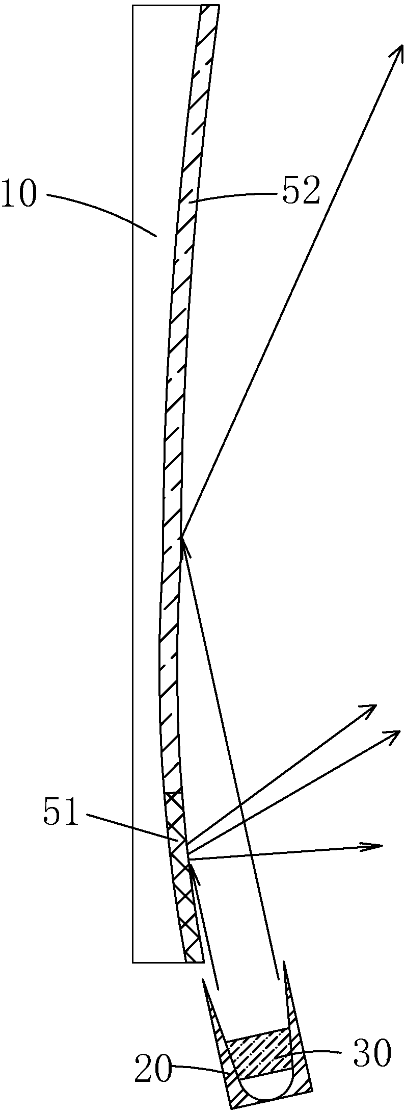
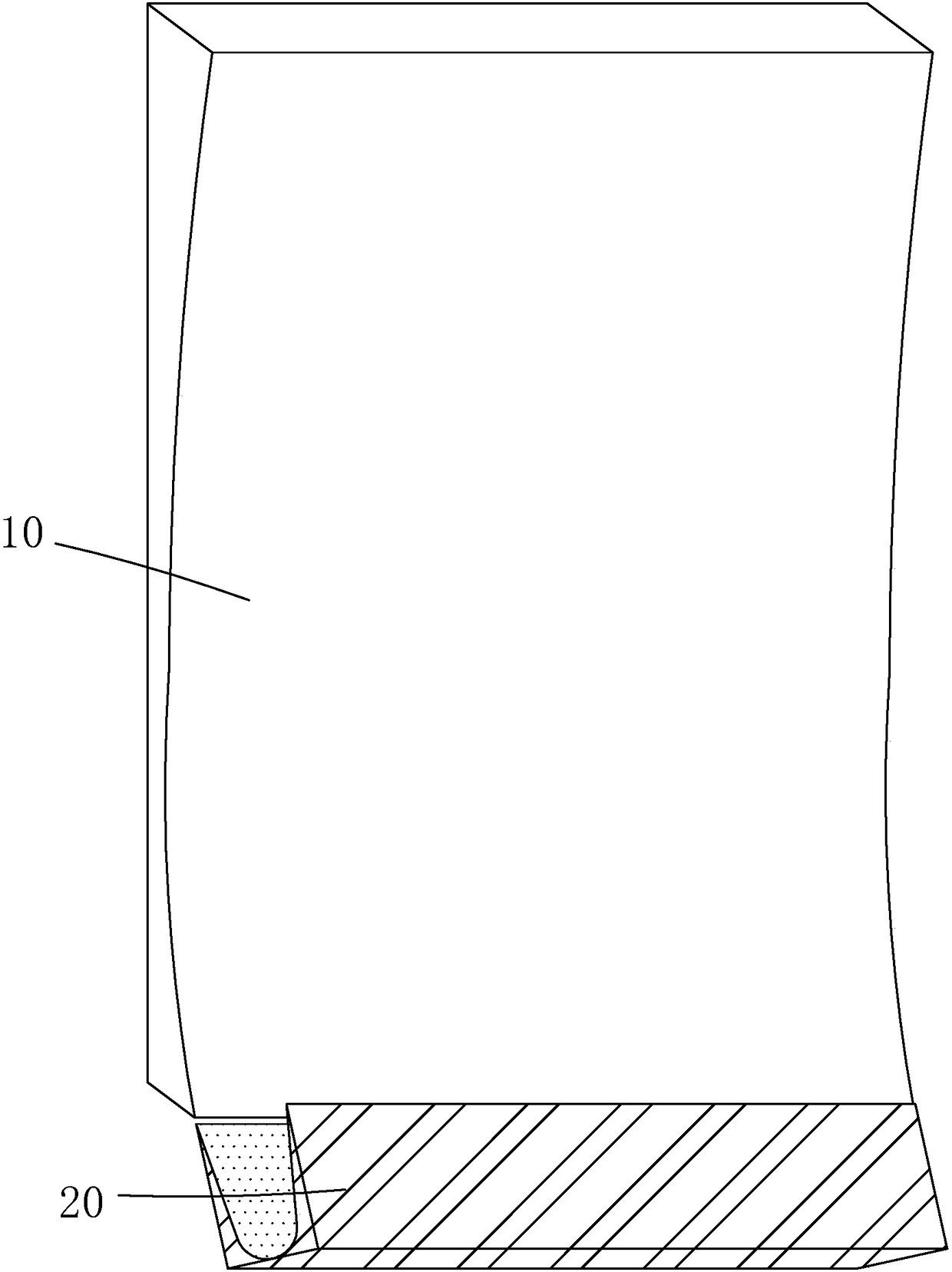
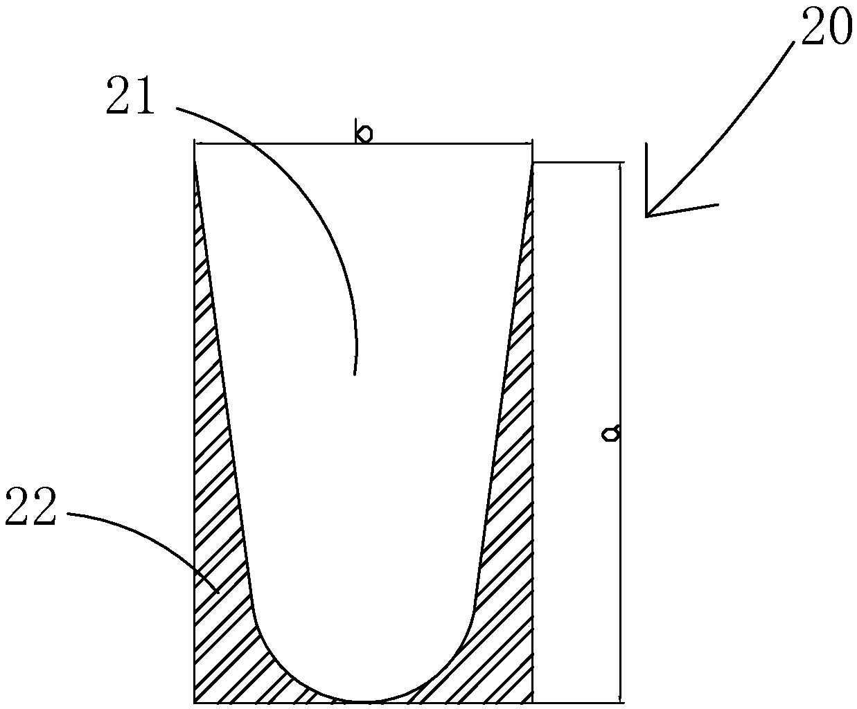
[0035] see Figure 1 to Figure 6 , the present invention provides a backlight module, comprising: a backplane 10, a collimating mirror 20 arranged on one side of the backplane 10, a diffusion lens 30 arranged opposite to the collimating mirror 20, and a The light source 40 between the diffusion lens 30 and the collimating mirror 20;

[0036] The light source 40 is a light emitting diode;

[0037] The collimating mirror 20 is used to make the light emitted by the light source 40 collimated and incident on the back plate 10;

[0038] The diffusion lens 30 is used to diffuse the light incident on the backplane 10 to the left and right sides of the backplane 10;

[0039] The back plate 10 is used to reflect the light incident on the back plate ...


PUM


Abstract

The invention provides a backlight module and a liquid crystal display device. The backlight module comprises a back plate, a collimating mirror arranged on one side of the back plate, a diffusing lens opposite to the collimating mirror as well as a light source arranged between the diffusing lens and the collimating mirror, wherein the light source is an LED (light emitting diode), light rays emitted by the light source are shot to the back plate in a collimating manner by means of the collimating mirror, the light rays shot to the back plate are diffused to the left and right sides of the back plate by means of the diffusing lens, the light rays shot to the back plate are reflected by the back plate, the light rays are diffused on the upper and lower sides of the back plate, further, thelight rays emitted by the light source are uniformly diffused to the display panel, and the brightness uniformity of the backlight module can be guaranteed under the condition that the single LED istaken as the light source.

Description

technical field [0001] The invention relates to the field of display technology, in particular to a backlight module and a liquid crystal display device. Background technique [0002] With the development of display technology, liquid crystal displays (Liquid Crystal Display, LCD) and other flat display devices are widely used in mobile phones, televisions, personal Various consumer electronic products such as digital assistants, digital cameras, notebook computers, and desktop computers have become the mainstream of display devices. [0003] Most of the liquid crystal display devices currently on the market are backlight liquid crystal display devices, which include a liquid crystal display panel and a backlight module. The working principle of the liquid crystal display panel is to place liquid crystal molecules between two parallel glass substrates. There are many vertical and horizontal small wires between the two glass substrates. The direction of the liquid crystal mo...

Claims


Application Information

Patent Timeline
IPC IPC(8): G02F1/13357
CPCG02F1/133603G02F1/133605G02F1/133606G02F1/133611G02F1/133607
Inventor 何小宇付琳琳
Owner HUIZHOU CHINA STAR OPTOELECTRONICS TECHNOLOGY CO LTD
Why Eureka
Try Eureka