
Display module and display device

A display module and display area technology, applied in character and pattern recognition, print image acquisition, instruments, etc., can solve problems such as uneven air layer between light guide plate and reflective layer, lower fingerprint recognition accuracy, and fingerprint sensor interference. Achieve the effect of ensuring brightness uniformity, avoiding brightness reduction, and improving accuracy

Active Publication Date: 2020-10-02
XIAMEN TIANMA MICRO ELECTRONICS
View PDF6 Cites 2 Cited by
  • Summary
  • Abstract
  • Description
  • Claims
  • Application Information

AI Technical Summary

Problems solved by technology

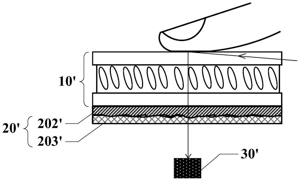
However, since the film material of each film layer in the backlight module is not flat, and the pressing of fingers will cause slight deformation of the light guide plate, an uneven air layer will be formed between the light guide plate and the reflective layer, and Newton’s rings will be generated.
The generation of Newton rings will interfere with the fingerprint sensor and reduce the accuracy of fingerprint recognition

Method used


Image

  • Display module and display device
  • Display module and display device
  • Display module and display device

Examples


Embodiment Construction

[0027] Various exemplary embodiments of the present invention will now be described in detail with reference to the accompanying drawings. It should be noted that the relative arrangements of components and steps, numerical expressions and numerical values ​​set forth in these embodiments do not limit the scope of the present invention unless specifically stated otherwise.

[0028] The following description of at least one exemplary embodiment is merely illustrative in nature and in no way taken as limiting the invention, its application or uses.

[0029] Techniques, methods and devices known to those of ordinary skill in the relevant art may not be discussed in detail, but where appropriate, such techniques, methods and devices should be considered part of the description.

[0030] In all examples shown and discussed herein, any specific values ​​should be construed as exemplary only, and not as limitations. Therefore, other instances of the exemplary embodiment may have dif...


PUM

PropertyMeasurementUnit
thicknessaaaaaaaaaa
thicknessaaaaaaaaaa

Abstract

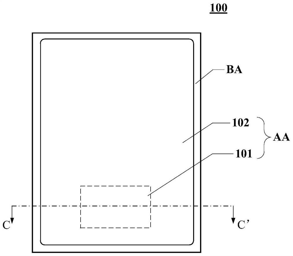
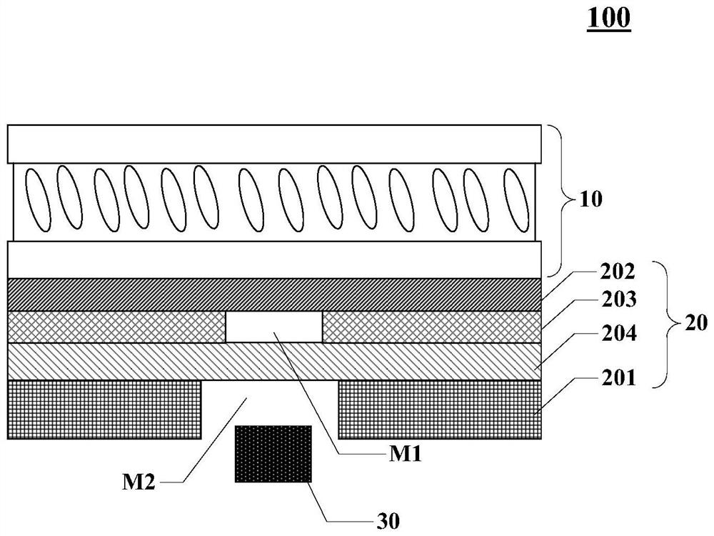
The invention discloses a display module and a display device, and relates to the technical field of display, and the display module comprises a display panel which comprises a display region and a non-display region at least partially surrounding the display region; a backlight module which is located on the side, away from the light emitting face of the display module, of the display panel and comprises a substrate, a light guide plate, a first reflecting layer and a second reflecting layer; and a light sensing element which is located on the side, away from the display panel, of the backlight module. Due to the fact that the first reflecting layer is provided with the first through hole, a large gap is formed between the light guide plate and the first reflecting layer, an uneven air layer can be prevented from appearing between the first reflecting layer and the light guide plate, the generation of Newton rings is effectively restrained, and the accuracy of optical fingerprint recognition is improved. Besides, the backlight module further comprises a second reflecting layer, the second reflecting layer covers the first through hole, light supplementing can be conducted on the fingerprint recognition area, it is avoided that after part of the first reflecting layer is removed, the display brightness of the area is reduced, and the brightness uniformity of the display deviceis guaranteed.

Description

technical field [0001] The present invention relates to the field of display technology, and more specifically, to a display module and a display device. Background technique [0002] With the development of display technology and full-screen technology, display panels with fingerprint recognition functions have gradually spread to every corner of our lives. Since fingerprints are inherent in the human body and uniquely distinguishable from others, in-screen fingerprint recognition technology with a high screen-to-body ratio is widely used in the display screens of electronic devices such as mobile phones and tablet computers. for identity verification. [0003] At present, fingerprint recognition technology mainly recognizes fingerprints by detecting the difference in the intensity of reflected light from fingerprint valleys and ridges. The reflected light carrying fingerprint information sequentially penetrates the display panel and backlight module and is finally receive...

Claims


Application Information

Patent Timeline
Patent Type & Authority Applications(China)
IPC IPC(8): G06K9/00G06F3/042
CPCG06F3/042G06V40/1324G06V40/1318
Inventor 谢天旭
Owner XIAMEN TIANMA MICRO ELECTRONICS
Learn More