

Elastic power generation device and application thereof
A technology for power generation devices and driving devices, which is applied to electromechanical devices, electric vehicles, electrical components, etc., can solve problems such as waste, power loss, and increase overall energy, and achieve high energy conversion rate, low failure rate, and reasonable overall structure. Effect
- Summary
- Abstract
- Description
- Claims
- Application Information
AI Technical Summary
Problems solved by technology
Method used
Image


Examples
Embodiment 1
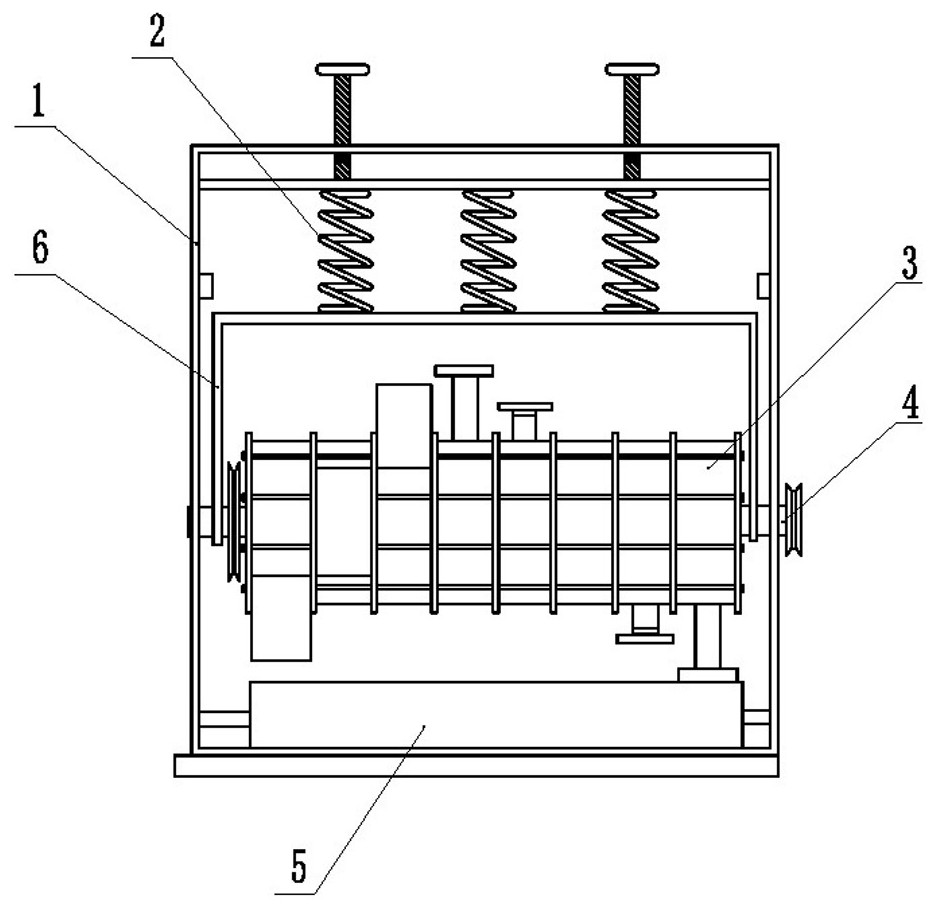
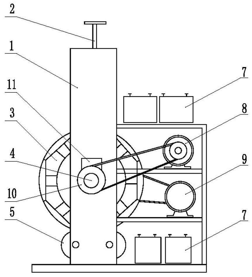
[0035] Embodiment 1: as Figures 1 to 8 As shown, an elastic power generation device includes a suspension unit 2 that applies pressure to the rotor 3, and the rotor 3 is suspended under the suspension unit 2. The drive device 9 drives the rotor 3 to rotate, and the rotor 3 drives the power generation device 8 to generate electricity; the rotor 3 It includes several coaxial turntables 3-2 arranged at intervals, and a power conversion unit 3-4 is arranged on the circumferential surface of each turntable 3-2; the several turntables 3-2 are sleeved on the same rotating shaft 4, and the turntable 3-2 It is linked with the driving device 1, and the rotating shaft 4 is linked with the power generation device 6;
[0036] The power conversion unit 3-4 includes a displaceable rod body 3-414 arranged on the turntable 3-2, the outer end of the rod body 3-414 is integrally connected with a base 3-415; the side of the rod body 3-414 is provided with an oblique connecting rod 3-413, the in...
Embodiment 2
[0056] Embodiment 2: as Figure 6 As shown, the power conversion unit 3-4 includes a cam 3-422 sleeved outside the rotating shaft 4 through a one-way bearing 3-420, a guide ring 3-416 fixed on the circular surface of the turntable 3-2, and a guide ring 3-416. Socket 3-419 is arranged on the circular surface of the turntable 3-2 inside the -416; the rod body 3-414 is inserted in the guide ring 3-416; the lower end of the rod body 3-414 is integrally connected with a base 3-415, The upper end is provided with a plug 3-418, and the plug 3-418 is inserted into the aforementioned socket 3-419; a return spring 3-417 is provided between the plug 3-418 and the socket 3-419; The connecting rod 3-413, the inner end of the oblique connecting rod 3-413 is hingedly linked with the aforementioned cam 3-422.
[0057] Before the application work, the pressure on the rotor 3 is adjusted by the hand wheel. After the adjustment, the drive device 9 is started, and the drive device 9 drives the p...
PUM
 Abstract
Description
Claims
Application Information