Supercharge Your Innovation With Domain-Expert AI Agents!

Zoom system

A magnification ring and magnification technology, which is applied in the field of magnification system, can solve problems such as wear, deformation, and magnification errors detected by components, and achieve the effects of improving measurement accuracy, eliminating errors, and prolonging service life

Inactive Publication Date: 2021-01-19
SINTAI OPTICAL SHENZHEN CO LTD +1
View PDF5 Cites 0 Cited by
  • Summary
  • Abstract
  • Description
  • Claims
  • Application Information

AI Technical Summary

Problems solved by technology

[0005] The technical problem to be solved by the present invention is to provide a zoom system that uses non-contact To detect the magnification in a way to solve the problems caused by deformation or wear between components due to contact

Method used


Image

  • Zoom system

Examples


Embodiment Construction

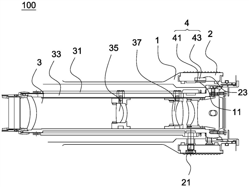
[0018] see figure 1 One embodiment of the zoom system 100 of the present invention includes a main body 1 , a zoom ring 2 , an optical lens group 3 , a conversion unit 4 and a processing unit (not shown). Among them, the zoom ring 2 rotates relative to the main body 1 to control the optical lens group 3, thereby adjusting the magnification of the zoom system 100, and the conversion unit 4 is used to convert the rotation information (such as the rotation angle or the number of rotations) of the zoom ring 2 An electrical signal corresponding to the magnification of the zoom system 100 is generated, and the processing unit can calculate the magnification of the zoom system 100 according to the electrical signal. The assembly of these components is detailed below:

[0019] It is worth noting that the zoom system 100 is suitable for devices requiring optical zoom, such as sighting devices, telescopes, distance measuring devices, and camera barrels. Wherein, the aiming device is t...


PUM


Abstract

The invention relates to a zoom system. The zoom system comprises a body, an optical lens group, a zoom ring and a conversion unit, and the optical lens group is arranged in the body. The zoom ring issleeved on the body and is used for rotating relative to the body to control the optical lens group so as to adjust the magnification of the zoom system. The conversion unit comprises a sensing unitand a reference assembly, and the rotation of the zoom ring enables the reference assembly to generate displacement, so that the sensing unit outputs an electric signal corresponding to the multiplying power of the zoom system, wherein the sensing unit is separated from the reference assembly by a preset distance.

Description

technical field [0001] The present invention relates to a zoom system, in particular to a zoom system that detects magnification in a non-contact manner. Background technique [0002] A traditional zoom system often includes an optical lens group, and the optical lens group includes an inner lens barrel and an outer lens barrel. During operation, the outer lens barrel is rotated relative to the inner lens barrel, so that the first lens and the second lens in the inner lens barrel move two different distances along the axial direction of the inner lens barrel, so as to achieve variable double function. [0003] In addition, the zoom system usually detects the magnification by using a pogo pin (Pogo Pin) and a resistance strip, wherein the resistance strip is set on the inner lens barrel, and the pogo pin is set on the outer lens barrel and contacts the Resistor strips. When the outer lens barrel is rotated relative to the inner lens barrel, the pogo pin will slide on the r...

Claims


Application Information

Patent Timeline
IPC IPC(8): G02B7/02G02B7/04G02B7/10
CPCG02B7/021G02B7/04G02B7/102
Inventor 周鸿棋张家淦
Owner SINTAI OPTICAL SHENZHEN CO LTD
Features
  • R&D
  • Intellectual Property
  • Life Sciences
  • Materials
  • Tech Scout
  • Unparalleled Data Quality
  • Higher Quality Content
  • 60% Fewer Hallucinations
Learn More