Multifunctional decorative storage rack convenient to use
A storage rack and multi-functional technology, applied in the field of storage racks, can solve the problems of single display effect that cannot be rotated, labor-intensive, dust accumulation, etc., and achieve the effect of increasing the display effect
- Summary
- Abstract
- Description
- Claims
- Application Information
AI Technical Summary
Problems solved by technology
Method used
Image
Examples
Embodiment 1
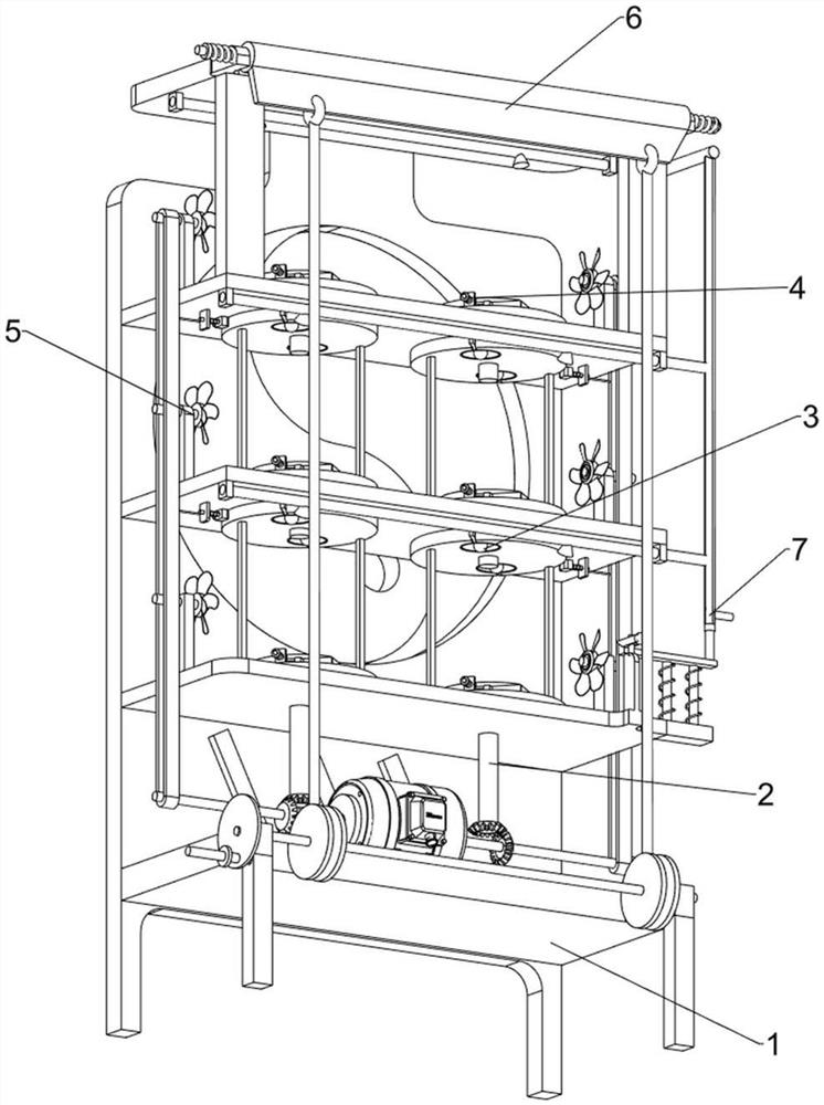
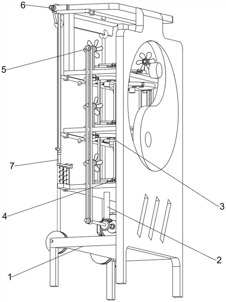
[0063] A convenient multifunctional decorative storage rack such as figure 1 and figure 2 As shown, it includes a base plate 1, a rotating mechanism 2 and a lighting mechanism 3, and the base plate 1 is provided with a rotating mechanism 2 symmetrically rotating left and right, and the base plate 1 is equipped with a lighting mechanism 3.
[0064]When a worker needs to store jade and flowers, the worker needs to place the jade and flowers on the rotating mechanism 2 first. After the worker places the jade and flowers on the rotating mechanism 2, the worker needs to control the rotation of the rotating mechanism 2, and the rotating mechanism 2 The rotation will drive the jade to rotate, and the rotation of the rotating mechanism 2 will drive the lighting mechanism 3 to rotate. After the lighting mechanism 3 rotates to the designated position, the lighting mechanism 3 will be turned on, and the light from the lighting mechanism 3 will shine on the jade and flowers. After the l...
Embodiment 2
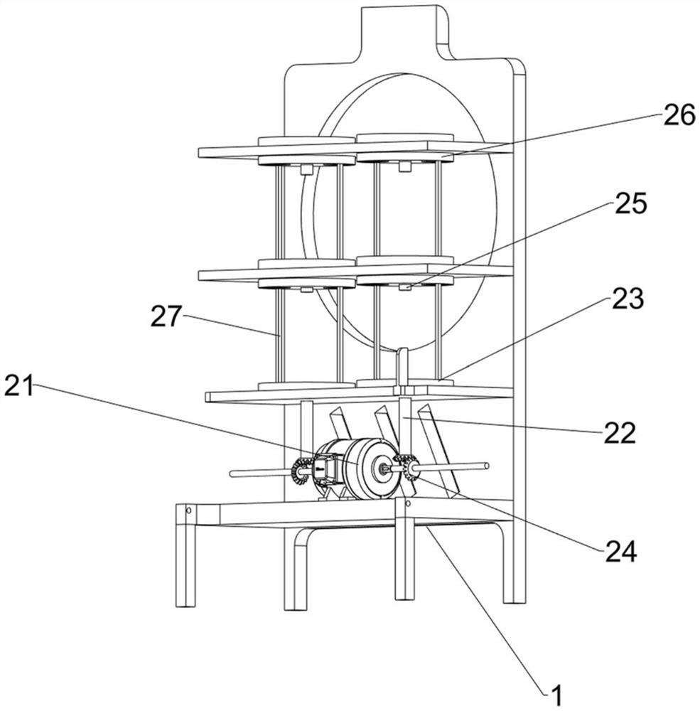
[0066] In a preferred embodiment of the present invention, as image 3 As shown, the rotating mechanism 2 includes a servo motor 21, a first rotating shaft 22, a first rotating disk 23, a bevel gear set 24, a second rotating shaft 25, a second rotating disk 26 and a connecting rod 27, and the middle of the lower part of the base plate 1 is fixed with a bolt. Servo motor 21, bottom plate 1 left and right is symmetrically provided with first rotating shaft 22, and first rotating disc 23 is fixedly connected on first rotating shaft 22, and bevel gear is connected between the bottom end of two first rotating shafts 22 and servo motor 21 output shafts Group 24, the bottom plate 1 upper left and right symmetrical rotation type is provided with the second rotating shaft 25, is fixedly connected with the second rotating disk 26 on the second rotating shaft 25, the bottom end of the second rotating shaft 25 is connected with the top of the first rotating disk 23, the corresponding first...
Embodiment 3
[0069] On the basis of Example 2, such as figure 1 , figure 2 and Figure 4 to Figure 8 As shown, the lighting mechanism 3 includes a lamp 31, a first contact switch 32, a first fixed block 33, a first elastic component 34, a second contact switch 35 and an electric wire 36, and the bottoms of the first turntable 23 and the second turntable 26 are left and right A lamp 31 is arranged symmetrically, a first contact switch 32 is symmetrically arranged on the outer walls of the first turntable 23 and the second turntable 26, and a first fixed block 33 is arranged symmetrically on the left and right sides of the bottom plate 1, and a sliding type is arranged inside the first fixed block 33. An elastic assembly 34, the inner end of the first elastic assembly 34 is fixedly connected with the second contact switch 35, the base plate 1 is equipped with an electric wire 36, the end of the electric wire 36 is connected with the second contact switch 35, and the second contact switch 3...
PUM
 Abstract
Description
Claims
Application Information
 - R&D
- Intellectual Property
- Life Sciences
- Materials
- Tech Scout
- Unparalleled Data Quality
- Higher Quality Content
- 60% Fewer Hallucinations
Browse by: Latest US Patents, China's latest patents, Technical Efficacy Thesaurus, Application Domain, Technology Topic, Popular Technical Reports.
© 2025 PatSnap. All rights reserved.Legal|Privacy policy|Modern Slavery Act Transparency Statement|Sitemap|About US| Contact US: help@patsnap.com


