High-precision multi-dimensional adjusting device

A multi-dimensional adjustment and high-precision technology, applied in medical science, internal bone synthesis, internal fixator, etc., can solve the problems of component fit gap error, cumbersome adjustment, long adjustment time, etc., saving valuable time, reducing the number of parts, Easy to use effect

A multi-dimensional adjustment and high-precision technology, applied in medical science, internal bone synthesis, internal fixator, etc., can solve the problems of component fit gap error, cumbersome adjustment, long adjustment time, etc., saving valuable time, reducing the number of parts, Easy to use effect

CN112244975APending Publication Date: 2021-01-22ι™ˆθšδΌ +1

Image

  • High-precision multi-dimensional adjusting device
  • High-precision multi-dimensional adjusting device
  • High-precision multi-dimensional adjusting device

Examples


Embodiment 1

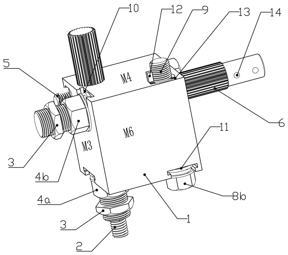
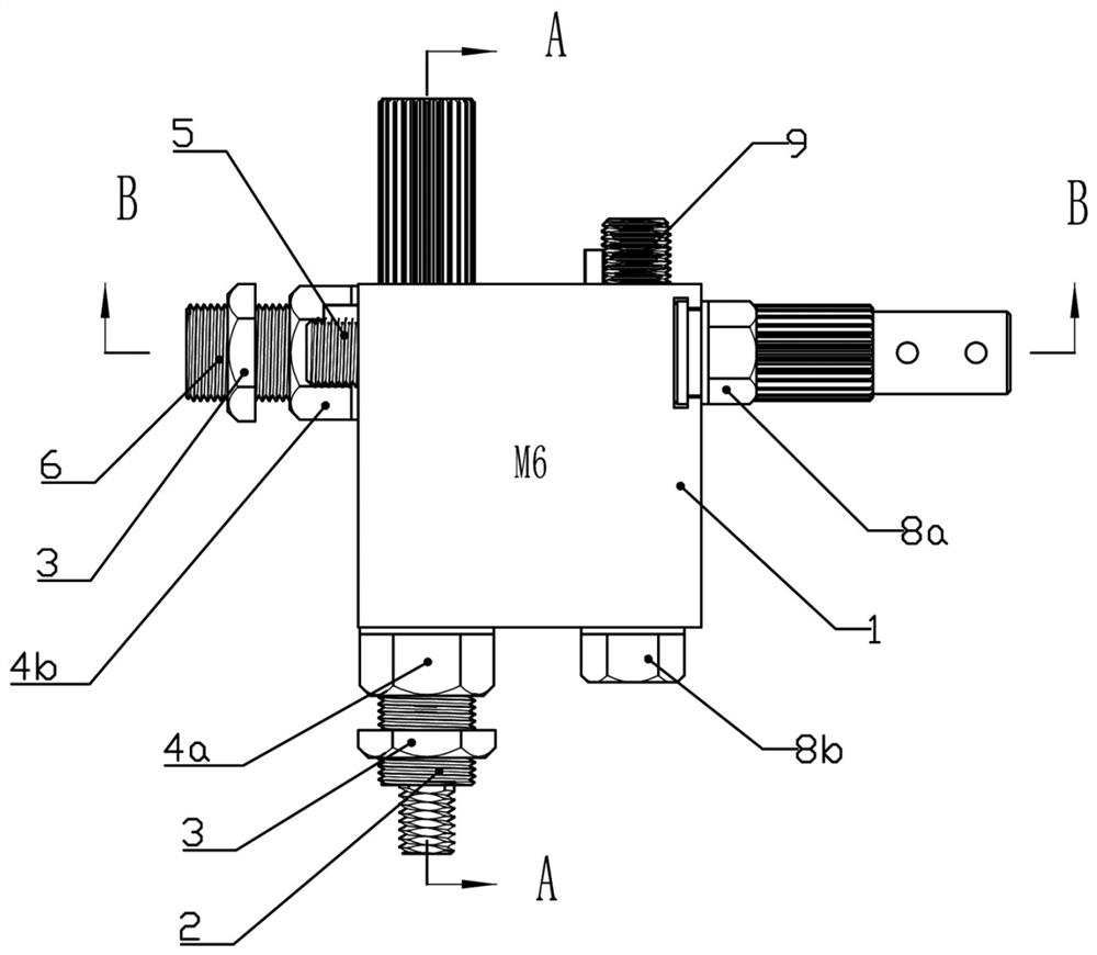
[0042]Example 1: Such asfigure 1 The four-dimensional adjustment device shown in the figure shows that the device includes a four-dimensional control seat 1, a lead screw gear shaft 1, a positioning nut 3, an axial non-shedding nut 4a, an axial non-shedding nut 2 4b, and a rack wire Bar one 5, screw gear shaft two 6, eccentric adjusting sleeve 7, steering non-shedding nut one 8a, steering non-shedding nut two 8b, rack screw two 9, and patch plates. Specifically, you can also passFigure 3-Figure 6 Learn the structure of the device and the cooperating relationship of the components from multiple sides and inside.

[0043]The specific structure of the four-dimensional control seat 1 involved in the device can be found inFigure 7-14, The drawings show in detail the relationship between the sides and internal holes of the four-dimensional control seat 1. It can be seen from the figure that the four-dimensional control seat 1 includes two shaft holes, namely a vertical shaft hole 15a and a t...

Embodiment 2

[0054]Embodiment 2: On the basis of embodiment 1, an eccentric adjusting sleeve is further fitted in the vertical connection hole. The specific structure of the eccentric adjusting sleeve 7 is attachedFigure 18 As shown in the figure, it can be seen that the inner cavity of the tube body 71 is an eccentric cavity 75, and the end of the tube body 71 is provided with a recess 72 formed by a side gap, and the gear section of the screw gear shaft is matched with this Give way to slot 72. One side of the relief groove area 72 has a straight groove bottom surface 73 and the other side has an arc groove bottom surface 74.

[0055]The function of the eccentric adjusting sleeve is to improve the reasonable gap between the gear and the rack. It can prevent the loosening of the gap caused by the meshing of the gear and the rack, further reducing the matching gap between the components, and improving the adjustment accuracy. In order to ensure the installation stability of the eccentric adjusting ...

Embodiment 3

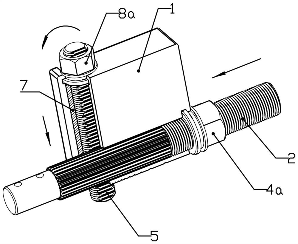
[0056]Embodiment 3: A high-precision two-dimensional adjustment device, which includes a base, a screw gear shaft, an axial non-shedding nut, a rack screw, a steering non-shedding nut, and the like. For details, seefigure 2 As shown, the base includes a shaft perforation along a linear dimension, and there is another perforation perpendicular to the shaft perforation, and the two perforations intersect, which is called a hanging hole.

[0057]The screw gear shaft, the axial non-shedding nut, the rack screw and the steering non-shedding nut, etc. are the same as or similar to the first embodiment. Specifically, the screw gear shaft includes a thread section at the first section and a gear section at the tail section. The screw gear shaft is matched and sleeved on the shaft after perforation, and the gear section is located at the intersection of the two perforations, and the nut does not fall off in the axial direction. The threaded section of the screw gear shaft, the nut and the shaft...


PUM


Abstract

The invention discloses a high-precision multi-dimensional adjusting device. A base of the high-precision multi-dimensional adjusting device comprises at least one shaft penetrating hole, and verticalconnecting holes are perpendicular to the corresponding shaft penetrating holes correspondingly. After lead screw gear shafts are arranged in the corresponding shaft penetrating holes in a matched and sleeving manner, gear sections of the lead screw gear shafts are located at the intersection of the two penetrating holes, and axial non-disengaging nuts are arranged on the threaded sections of thelead screw gear shafts. The nuts and the head ends of the shaft penetrating holes are provided with first non-disengaging structures. A rack portion is arranged on one side of each rack lead screw, and each steering non-disengaging nut is arranged on the threaded section of the corresponding rack lead screw. The nuts and the head ends of the vertical connecting holes are provided with second non-disengaging structures. After the rack lead screws are arranged in the vertical connecting holes in a matched and sleeving manner, the rack portions of the rack lead screws are engaged with the gear sections of the lead screw gear shafts. According to the high-precision multi-dimensional adjusting device, multi-dimensional independent axial adjustment and angle adjustment can be achieved. Adjusting operation becomes simple, and the high-precision multi-dimensional adjusting device is easy to use. The structure is compact, reasonable and simplified, the design is optimized, the number of adopted components is the minimum, and the precision degree is improved.

Description

Technical field[0001]The invention belongs to the technical field of adjusting the distal end aiming bracket of a locking screw of a femoral intramedullary nail, and in particular relates to a multi-dimensional aiming adjustment device for the distal end of an intramedullary nail.Background technique[0002]At present, femoral intramedullary nails are used clinically for femoral fractures, which is a minimally invasive treatment method for femoral fractures. Because the intramedullary nail is deformed to a certain extent after being implanted in the bone, it is often difficult to lock the distal nail. In order to reduce the difficulty of locking the nail at the distal end, a mechanical aiming device is generally used to improve the success rate of the nail locking. However, the basic principle of the mechanical aiming device used now is to adjust the offset of the aiming device through the positioning rod. The success rate of the first nail locking in actual clinical application is no...

Claims


Application Information

Patent Timeline
22 Jan 2021
Publication
CN112244975A
IPC
A61B17/72; A61B17/90; A61B17/76
CPC
A61B17/725; A61B17/74; A61B17/88; A61B17/90
Inventors
ι™ˆθšδΌ; ι›’εˆηΎ€