Multi-stage screening mechanism, concrete sand and gravel screening device

A sieving device and sieving technology, applied in the fields of sieving, solid separation, chemical instruments and methods, etc., can solve the problems of limited sieve movement range, low sieving efficiency, and low utilization of sieving material space, achieving The effect of ensuring stability

Active Publication Date: 2022-04-22
郑州市金禄市政工程有限公司
View PDF8 Cites 3 Cited by
  • Summary
  • Abstract
  • Description
  • Claims
  • Application Information

AI Technical Summary

Problems solved by technology

However, when the above-mentioned prior art screens materials, as disclosed in patent application 201711362216.2, it discloses a multi-stage screening system for organic fertilizers, which uses cam drive and spring reset to realize the shaking of the hopper. This contact transmission method In order to ensure the accuracy of the transmission and prevent excessive rebound impact force, the range of motion should not be too large, resulting in limited motion range of the screen and low screening efficiency; such as the agricultural three-stage vibrating screen disclosed in patent application 201721736026.8 or patent application 201721885664.6 A disclosed sieving device in the production process of florfenicol powder adopts the linear reciprocating motion of the sieve for sieving. The structure of the sieve plate of this technology is mostly a planar structure, that is, there are mostly meshes that conduct up and down. Holes, combined with the vibration-type or swing-type reciprocating linear motion of the prior art, lead to the fact that when the material is sieved, its discharge points are mostly concentrated at the bottom of the screen, and the space utilization rate of the sieve is low; it also leads to Low sieving efficiency technical problems

Method used


Image

  • Multi-stage screening mechanism, concrete sand and gravel screening device
  • Multi-stage screening mechanism, concrete sand and gravel screening device
  • Multi-stage screening mechanism, concrete sand and gravel screening device

Examples


Embodiment 1

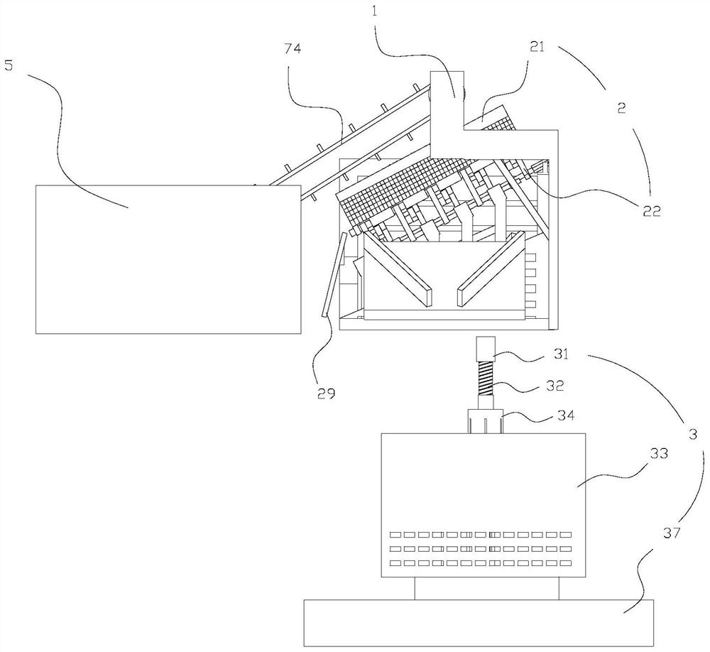
[0069] Such as figure 1 As shown, this embodiment discloses a multi-stage screening mechanism for sequential screening in space, including a frame 1 , a primary screening device 2 , and a secondary screening device 3 . The primary screening device 2 and the secondary screening device 3 are sequentially arranged on the frame 1 from top to bottom, and the secondary screening device 3 is used for secondary screening of the materials screened by the primary screening device 2 . The size of the first mesh in the first screening device 2 is greater than the size of the second mesh of the secondary screening device 3, that is, the particle size ratio of the first material falling from the first mesh in the first screening device 2 The second material falling from the second mesh of the secondary screening device 3 is a material with a large particle size.

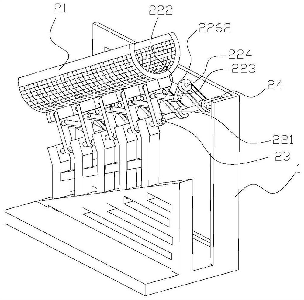
[0070] Such as Figure 1-3 As shown, the primary screening device 2 includes an upward arc screen 21, a swing mechanism 22, a ...

Embodiment 2

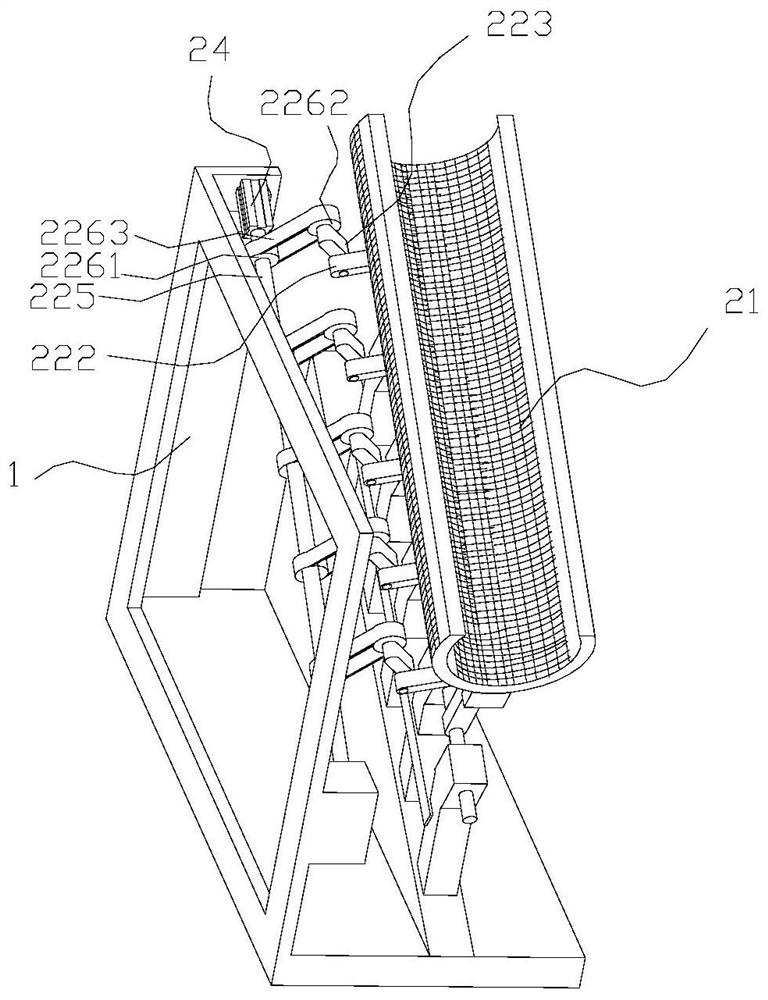
[0085] Such as figure 2 , 3 As shown, the difference between this embodiment and the above-mentioned embodiments is that there are multiple swing mechanisms 22 distributed at intervals along the length direction of the circular arc screen 21 . The other end of each third rotating arm 223 is connected with a driven shaft 224, and also includes a driving shaft 225, the driving shaft 225 is in rotation with the frame 1, and the end of the driving shaft 225 is connected with the output shaft of the first drive motor 24, The transmission between the driving shaft 225 and each driven shaft 224 is respectively through a set of transmission components. The transmission assembly of the present invention can be the belt transmission device of prior art, comprises primary screening driving pulley 2261, primary screening driven pulley 2262, primary screening belt 2263, primary screening primary pulley 2261 is connected on the drive shaft 225 , the primary screening driven pulley 2262 i...

Embodiment 3

[0088] Such as Figure 10 , 11 As shown, the difference between this embodiment and the above-mentioned embodiments is that it also includes a climbing type scraper conveying device and a stacking bin 5 . The opening of the accumulation bin 5 is upward for accumulating the materials to be screened. The lower end of the climbing-type scraper conveying device is limited in the accumulation bin 5, and the higher end of the climbing-type scraper conveying device is exposed to the opening of the accumulation bin 5 and extends upwards, from the climbing-type scraper conveying device The falling material can fall into it through the opening end of the circular arc screen cloth 21 .

[0089] The climbing type scraper conveying device comprises a feeding motor 71, a feeding driving wheel 72, a feeding driven wheel (not shown in the figure), and a feeding belt 74. The driven wheel can be connected on the feeding driven shaft, and the two ends of the feeding driven shaft are respectiv...


PUM


Abstract

The invention discloses a multi-stage screening mechanism for sequential screening in spatial positions. The primary screening device and the secondary screening device are arranged sequentially from top to bottom. The first driving motor is used to drive the swing mechanism to swing, and then drive the circular arc screen. The net swings; the material screened from the arc screen can fall into the secondary screening device; the output shaft of the second drive motor is connected to the top of the connecting rod, and the bottom of the connecting rod extends downward; the sleeve is set on the There is a gap between the periphery of the connecting rod and the connecting rod; moving the lower pressing piece down can drive the movable block to slide down so that the other end of the second connecting rod sticks out of the through groove; the secondary screen is connected to the sleeve; The secondary screen includes a bottom screen and a side screen, and the bottom screen and the side screen are enclosed to form a screen structure with an opening at the top and connections around and at the bottom; the secondary screen can rotate relative to the chassis. The invention also discloses a concrete gravel screening device. The invention has the advantage of high screening efficiency.

Description

technical field [0001] The invention relates to the technical field of construction engineering material processing, in particular to a multi-stage screening mechanism and a concrete sand screening device. Background technique [0002] The material screening technology is to realize the separation between the material with larger particle size and the material with smaller particle size through the filtering function of the mesh in the screen. When it is necessary to classify the particle size of the material or to screen the material multiple times to ensure the quality of the screening, a multi-stage screening mechanism is required. [0003] For example, patent application 201711362216.2 discloses a multi-stage screening system for organic fertilizers. The first screening unit screens debris, the second screening unit screens out a particle size range and the third screening unit screens Particles in another particle size range are separated; multi-stage screening is carr...

Claims


Application Information

Patent Timeline
Patent Type & Authority Patents(China)
IPC IPC(8): B07B1/38B07B1/08B07B1/46
CPCB07B1/38B07B1/08B07B1/46
Inventor 曾维西
Owner 郑州市金禄市政工程有限公司
Why Eureka
Try Eureka