Shell cutting, peeling and chamfering machine

A technology of chamfering machine and shell, applied in other manufacturing equipment/tools, manufacturing tools, etc., can solve the problems of low processing efficiency and long processing cycle

Inactive Publication Date: 2021-01-22
重庆翔睿捷自动化设备股份有限公司
View PDF12 Cites 0 Cited by
  • Summary
  • Abstract
  • Description
  • Claims
  • Application Information

AI Technical Summary

Problems solved by technology

[0003] However, according to the prior art, if a large quantity of steel wire pipes needs to be processed twice, different equipments are used to process them manually, which will lead to the defects of low processing efficiency and long processing cycle.

Method used


Image

  • Shell cutting, peeling and chamfering machine
  • Shell cutting, peeling and chamfering machine
  • Shell cutting, peeling and chamfering machine

Examples


Embodiment Construction

[0032] The following will clearly and completely describe the technical solutions in the embodiments of the present invention with reference to the accompanying drawings in the embodiments of the present invention. Obviously, the described embodiments are only some of the embodiments of the present invention, not all of them. Unless otherwise specified, the technical means used in the embodiments are conventional means well known to those skilled in the art.

[0033] In describing the present invention, it should be understood that the terms "longitudinal", "transverse", "upper", "lower", "front", "rear", "left", "right", "vertical", The orientations or positional relationships indicated by "horizontal", "top", "bottom", "inner", "outer", etc. are based on the orientations or positional relationships shown in the drawings, and are only for the convenience of describing the present invention, rather than indicating or It should not be construed as limiting the invention by impl...


PUM


Abstract

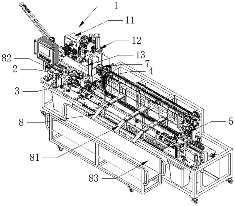
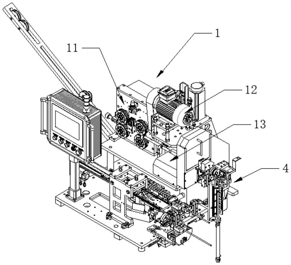
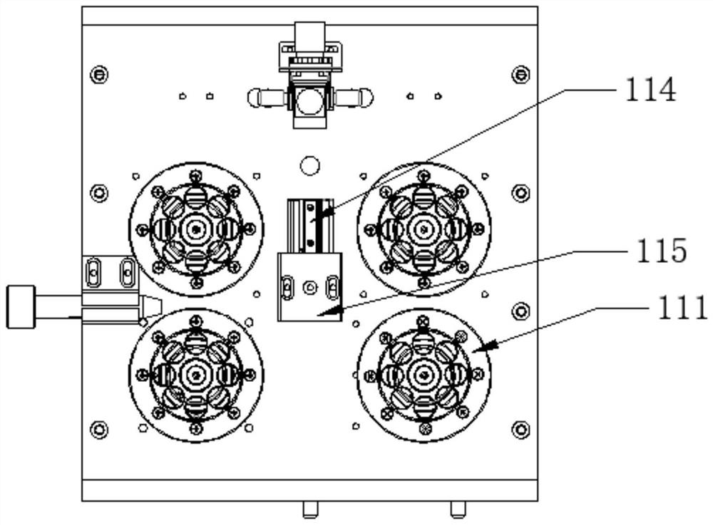
The invention discloses a shell cutting, peeling and chamfering machine, relates to the field of steel wire pipe machining devices, and particularly relates to improvement of structures of the steel wire pipe machining devices. The shell cutting, peeling and chamfering machine comprises a wire pre-feeding module, a chamfering module and a shell peeling module, wherein the wire pre-feeding module comprises a pipe feeding device, a pipe cutting device and a pipe clamping device; the chamfering module comprises a chamfering cutter, a chamfering rotating motor and a chamfering advancement cylinder; and the shell peeling module comprises a puncture cutter, a shell peeling puncture cylinder, a shell peeling rotating cylinder and a shell peeling electric cylinder. The shell cutting, peeling and chamfering machine can realize automatic realization of pipe feeding, pipe cutting and blanking, chamfering and shell peeling processes of steel wire pipes, and particularly relates to transfer of materials in blanking, chamfering and shell peeling multiple stations.

Description

technical field [0001] The invention belongs to the field of steel wire pipe processing equipment, and in particular relates to the improvement of the structure of the steel wire pipe processing equipment. Background technique [0002] The steel wire pipe includes the steel wire pipe inner core arranged in the innermost layer, the steel wire pipe inner shell arranged in the middle layer and the steel wire pipe shell arranged in the outer layer. The required length is cut, and the steel wire pipe is subjected to secondary processing according to the needs of use, such as chamfering the two ends of the inner core of the steel wire pipe set on the innermost layer and stripping the outer shell of the steel wire pipe to a certain length, etc. [0003] However, according to the prior art, if a large quantity of steel wire pipes needs to be processed twice, different equipments are used to process them manually, which will lead to the defects of low processing efficiency and long p...

Claims


Application Information

Patent Timeline
Patent Type & Authority Applications(China)
IPC IPC(8): B23P23/06
CPCB23P23/06
Inventor 喻洪江王正义
Owner 重庆翔睿捷自动化设备股份有限公司
Why Eureka
Try Eureka