A turning fixture for thin-walled parts

A thin-walled parts, turning technology, applied in the direction of metal processing machinery parts, clamping, manufacturing tools, etc., can solve the problem that it is impossible to avoid the deformation of the processed parts, it is impossible to achieve the processing accuracy, and it is not easy to ensure the perfect processing parts and positioning blocks Contact and other problems to achieve the effect of eliminating vibration and high precision

Active Publication Date: 2022-05-17
CHANGZHOU VOCATIONAL INST OF ENG
View PDF18 Cites 0 Cited by
  • Summary
  • Abstract
  • Description
  • Claims
  • Application Information

AI Technical Summary

Problems solved by technology

Especially when the surface of the inner hole of the processed part is a rough surface, it is not easy to ensure the perfect contact between the processed part and the positioning block
Therefore, it is impossible to avoid the deformation of the processed parts with the fixture designed by conventional technical solutions, so it is impossible to meet the requirements of machining accuracy, especially for precision parts (such as auto parts)

Method used


Image

  • A turning fixture for thin-walled parts
  • A turning fixture for thin-walled parts
  • A turning fixture for thin-walled parts

Examples


Embodiment 1

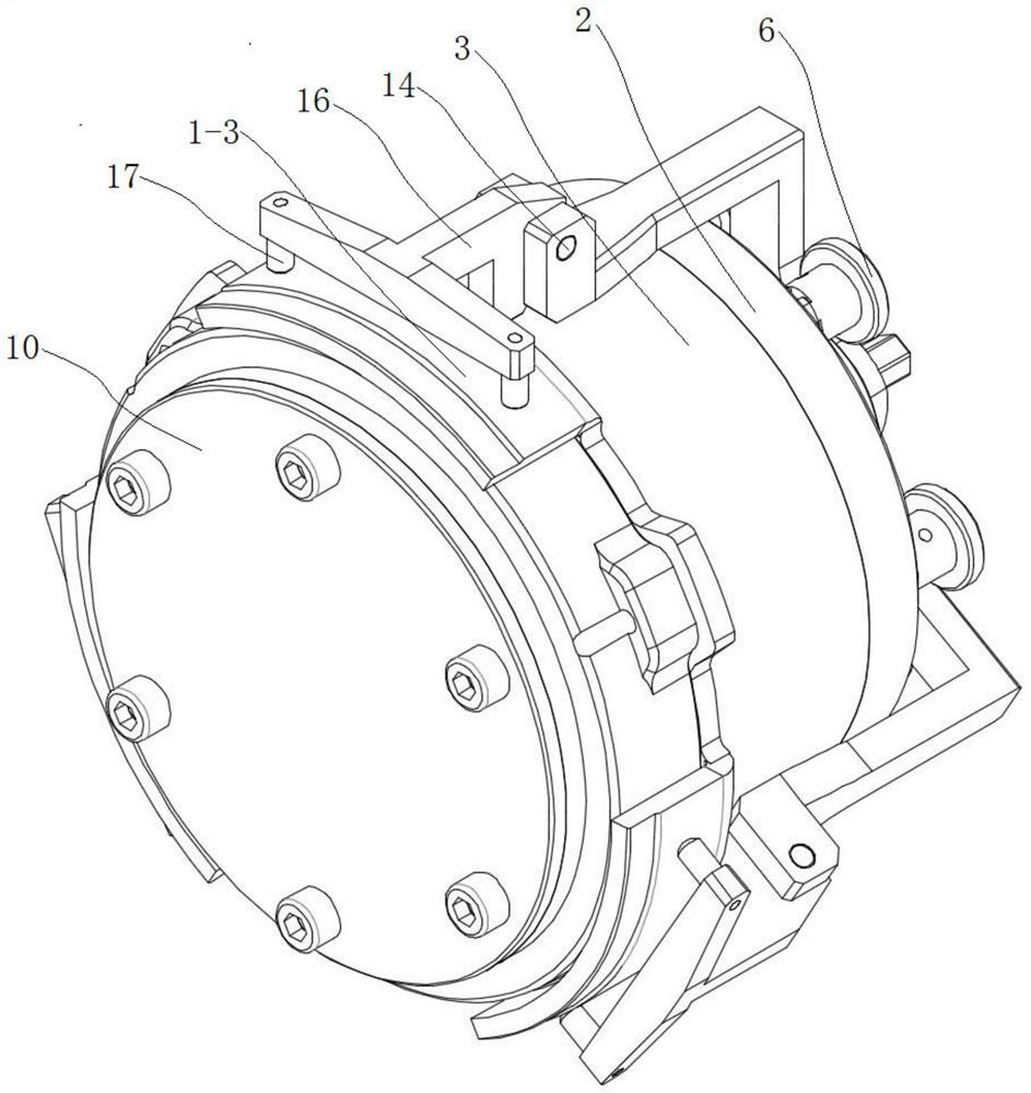
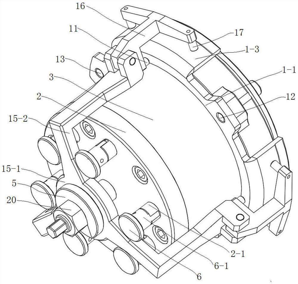
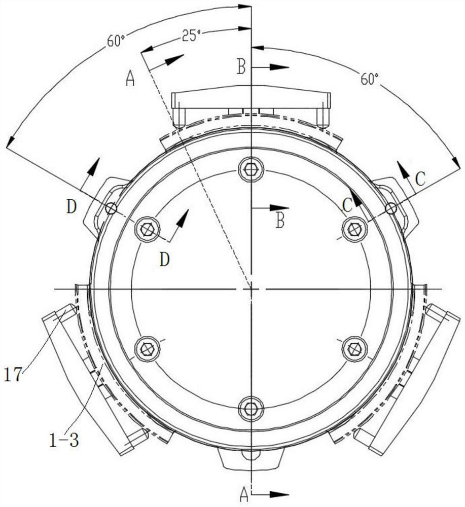
[0038] combine figure 1 , figure 2 and Figure 9, a kind of thin-walled part turning jig of the present embodiment comprises a cylindrical clamping body, and the clamping body includes a middle clamping body 3, a rear cover plate 2 fixed on the rear end surface of the middle clamping body 3, and a rear cover plate 2 fixed on the middle clamping body 3 The front cover plate 10 of the front end face, a step surface 3-1 is provided between the front outer peripheral surface of the intermediate folder body 3 and the rear outer peripheral surface of the intermediate folder body 3, and a cylindrical positioning cylinder is arranged on the stepped surface 3-1. Pin 13 and diamond-shaped positioning pin 12; after the front part of the middle clamp body 3 passes through the annular chassis 1-1 of the thin-walled part to be processed, the annular chassis 1-1 is matched with the stepped surface 3-1, and the stepped surface 3-1 Cylindrical locating pin 13 and rhombus locating pin 12 are...

Embodiment 2

[0050] The basic structure of a thin-walled part turning jig of this embodiment is the same as that of Embodiment 1, except that the angle between the first wedge surface and the axis of the cylindrical connecting portion is 8°.

Embodiment 3

[0052] The basic structure of a thin-walled part turning jig of this embodiment is the same as that of Embodiment 1, except that the angle between the first wedge surface and the axis of the cylindrical connecting portion is 10°.

[0053] The thin-walled part turning fixture of the present invention has simple structure, ingenious design, and convenient connection, and can well solve the positioning or clamping of the thin-walled part to be processed and the deformation during processing, thereby ensuring the accuracy of the thin-walled part to be processed Machining accuracy requirements.


PUM


Abstract

The invention discloses a thin-walled parts turning fixture, which comprises a cylindrical clamping body. The clamping body includes an intermediate clamping body, a rear cover plate fixed on the rear end surface of the intermediate clamping body, and a front cover fixed on the front end surface of the intermediate clamping body plate, a stepped surface is provided between the front outer peripheral surface of the intermediate folder body and the rear outer peripheral surface of the intermediate folder body, and cylindrical positioning pins and diamond-shaped positioning pins are arranged on the stepped surface; the front part of the intermediate folder body passes through After the annular chassis of the thin-walled parts is to be processed, the annular chassis is matched with the step surface, and the cylindrical positioning pin and the diamond-shaped positioning pin on the step surface are respectively inserted into two of the three holes on the annular chassis; It is provided with an inner support mechanism and a pressing plate mechanism that cooperate with each other to realize the fixing of the thin-walled parts to be processed. The invention can well solve the positioning or clamping of the thin-walled parts to be processed and the deformation in the processing process, thereby ensuring the processing accuracy requirements of the thin-walled parts to be processed.

Description

technical field [0001] The invention relates to a turning fixture, more specifically, to a turning fixture for thin-walled parts. Background technique [0002] When thin-walled parts need to be turned, the conventional technical solution is to place the part to be processed on the fixed positioning block of the fixture, which will cause deformation of the part to be processed when it is positioned or clamped. If the size of the positioning block is larger than the size of the processed part, the workpiece will be forcibly stretched when positioning the workpiece (because the processed part is a thin-walled part, it is easy to deform); if the positioning block is smaller than the processed part, the positioning A gap will be generated, and the processed part will be forcibly compressed and deformed when the pressure plate is clamped. Especially when the surface of the inner hole of the machined part is a rough surface, it is more difficult to ensure perfect contact between t...

Claims


Application Information

Patent Timeline
Patent Type & Authority Patents(China)
IPC IPC(8): B23Q3/00
CPCB23Q3/00B23Q2703/10
Inventor 夏晓平邱国仙金燕张在平吴芳
Owner CHANGZHOU VOCATIONAL INST OF ENG
Why Eureka
Try Eureka