
Grinding wheel correction system of cylindrical grinding machine

A calibration system and technology for cylindrical grinding machines, which are applied to grinding machines, parts of grinding machine tools, and machine tools designed for grinding the rotating surface of workpieces, etc., can solve the problems of affecting detection and correction, failure to detect grinding wheels, adjustment, etc., to ensure accuracy High performance, guaranteed stability, easy to detect the effect of correction

Inactive Publication Date: 2021-01-22
襄阳鹏图机电设备有限公司
View PDF8 Cites 0 Cited by
  • Summary
  • Abstract
  • Description
  • Claims
  • Application Information

AI Technical Summary

Problems solved by technology

[0005] Aiming at the deficiencies of the prior art, the present invention provides a grinding wheel calibration system for cylindrical grinders, which solves the problem that the grinding wheel calibration device is inconvenient to adjust the height of the laser emitting tube during detection, so that grinding wheels of different heights cannot be detected, and The laser emitting tube is not equipped with a supporting and stable device during the emission detection, which makes the laser emitting tube easy to shake and affects the problem of detection and correction

Method used


Image

  • Grinding wheel correction system of cylindrical grinding machine
  • Grinding wheel correction system of cylindrical grinding machine
  • Grinding wheel correction system of cylindrical grinding machine

Examples


Embodiment Construction

[0026] The technical solutions in the embodiments of the present invention will be clearly and completely described below with reference to the accompanying drawings in the embodiments of the present invention. Obviously, the described embodiments are only a part of the embodiments of the present invention, but not all of the embodiments. Based on the embodiments of the present invention, all other embodiments obtained by those of ordinary skill in the art without creative efforts shall fall within the protection scope of the present invention.

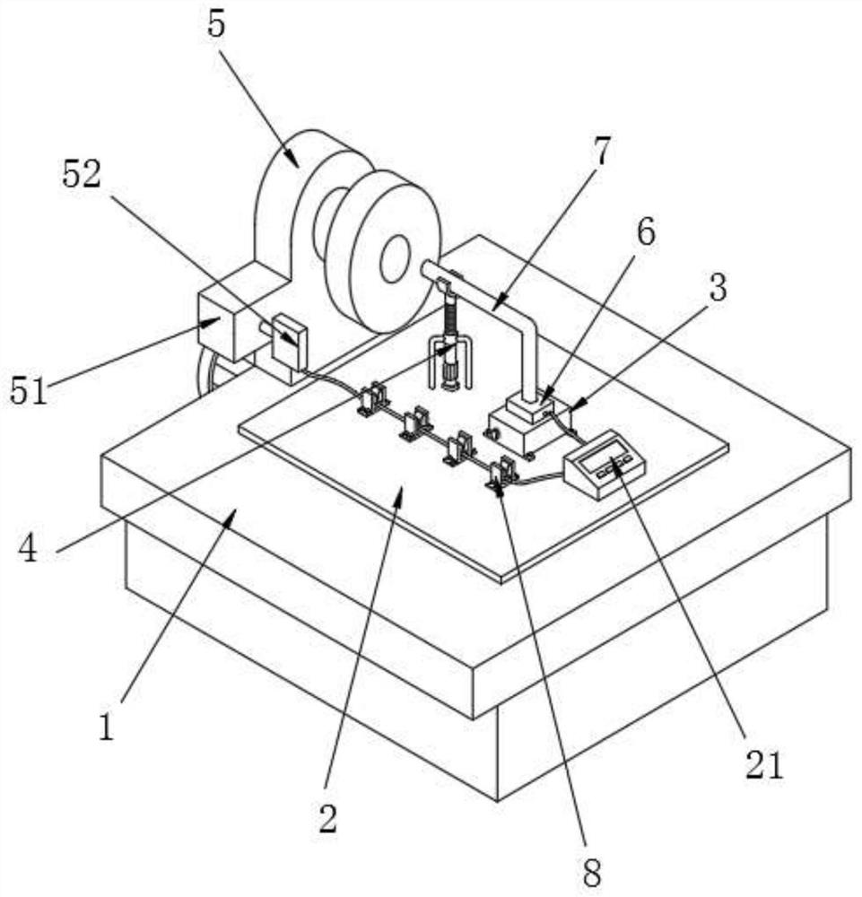
[0027] see figure 1 , the present invention provides a technical solution: a grinding wheel correction system for a cylindrical grinder, including a workbench 1, a base plate 2 is arranged at the middle position of the upper surface of the workbench 1, and a height adjustment is fixedly connected at the middle position of the upper surface of the base plate 2 Mechanism 3, and the upper surface of the substrate 2 is provided with a sta...


PUM


Abstract

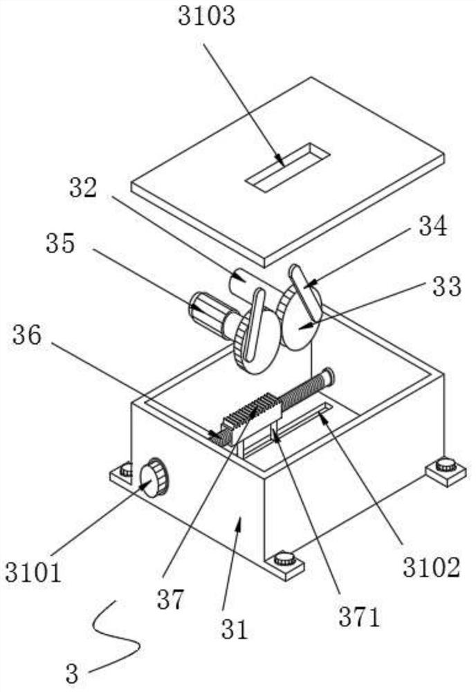
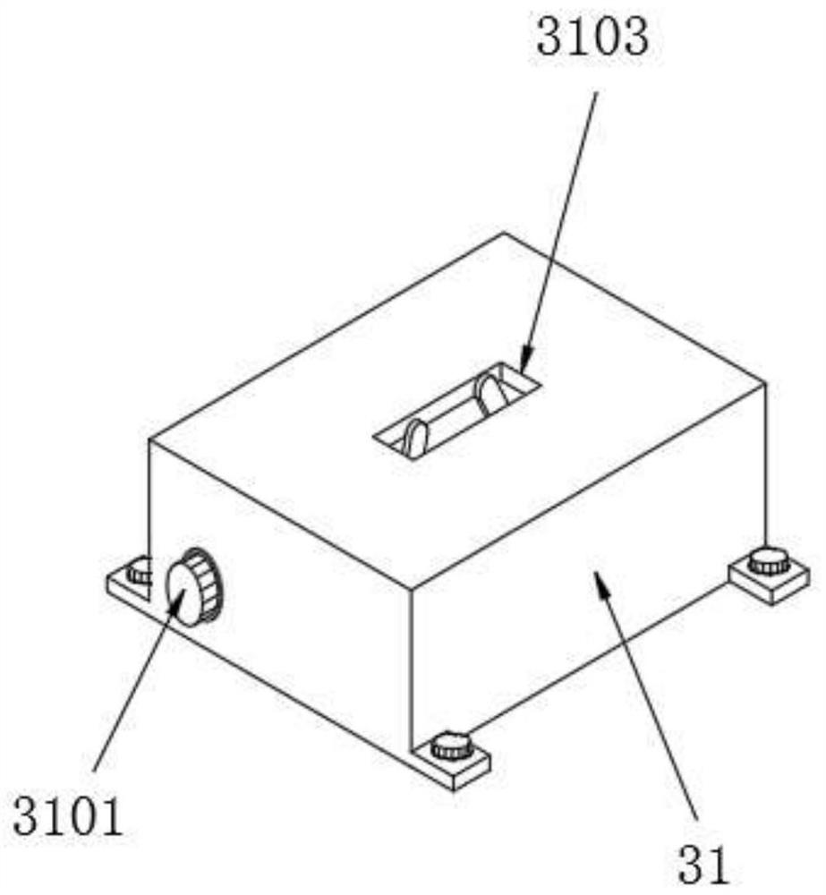
The invention discloses a grinding wheel correction system of a cylindrical grinding machine. The grinding wheel correction system comprises a workbench, wherein a base plate is arranged at the middleposition of the upper surface of the workbench; a height adjusting mechanism is fixedly connected to the middle position of the upper surface of the base plate; a stabilizing piece is arranged at theposition, close to the rear position of the height adjusting mechanism, of the upper surface of the base plate; and a vertical block is fixedly connected to the upper surface of the rear side of theworkbench. The invention relates to the technical field of cylindrical grinding machines. According to the grinding wheel correction system of the cylindrical grinding machine, the height adjusting mechanism is arranged, when grinding wheels with different heights are detected and corrected, a user only needs to rotate a knob to enable the knob to drive a rack block on a screw rod to move, the rack block can drive two gear discs to rotate, so that eccentric rods on the two gear discs can drive a laser sensor to move up and down, then the height of a laser emitting tube is adjusted, the grinding wheels with different heights can be detected and corrected conveniently, and then the accuracy of detection and correction is guaranteed.

Description

technical field [0001] The invention relates to the technical field of cylindrical grinding machines, in particular to a grinding wheel correction system for cylindrical grinding machines. Background technique [0002] Cylindrical grinding machine is a grinding machine for processing the outer surface and shoulder end surface of workpiece cylindrical, conical or other shapes, which are the most widely used, and can process various cylindrical conical outer surfaces and shoulder end surface grinding machines. In order to ensure The accuracy of the work of the cylindrical grinder requires frequent inspection and correction of the grinding wheel on the cylindrical grinder. [0003] The utility model with Chinese patent No. CN210335552U discloses a grinding wheel balance correction device for an inner ring channel grinder, which includes a grinder and an adjustment block. A processing table is provided in the middle of the top of the grinding machine, and a laser sensor is provi...

Claims


Application Information

Patent Timeline
Patent Type & Authority Applications(China)
IPC IPC(8): B24B49/12B24B49/00B24B5/00
CPCB24B49/12B24B49/00B24B5/00
Inventor 蔡启先蔡新江
Owner 襄阳鹏图机电设备有限公司
Learn More