New energy automobile charging pile

A technology of new energy vehicles and charging piles, applied in electric vehicle charging technology, charging stations, electric vehicles, etc., can solve the problems of inconvenient disassembly, different voltage levels, etc., and achieve the effect of saving time, saving energy, and avoiding accidental sliding

Inactive Publication Date: 2021-01-22
张杰
View PDF8 Cites 2 Cited by
  • Summary
  • Abstract
  • Description
  • Claims
  • Application Information

AI Technical Summary

Problems solved by technology

[0002] The function of the charging pile is similar to the refueling machine in the gas station. It can be fixed on the ground or wall, and installed in public buildings (public buildings, shopping malls, public parking lots, etc.) and residential area parking lots or charging stations. Charging various types of electric vehicles; however, existing charging piles have different voltage levels and can only charge a single type of vehicle, and a single charging pile is installed in public buildings (public buildings, shopping malls, public parking lots, etc.) It is not easy to disassemble when replacing in the parking lot or charging station of the residential area, which will bring a lot of workload and more working time to the replacement of old, damaged or different voltage level charging piles

Method used


Image

  • New energy automobile charging pile
  • New energy automobile charging pile
  • New energy automobile charging pile

Examples


specific Embodiment approach 1

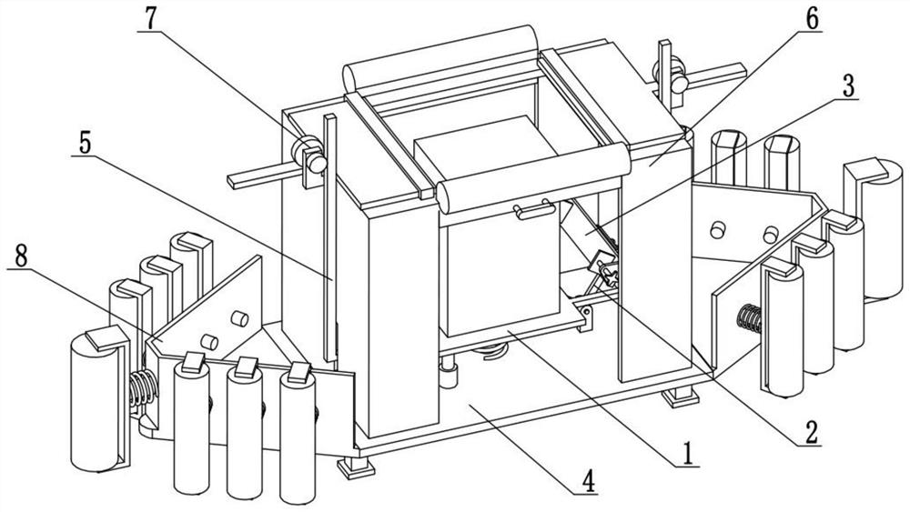
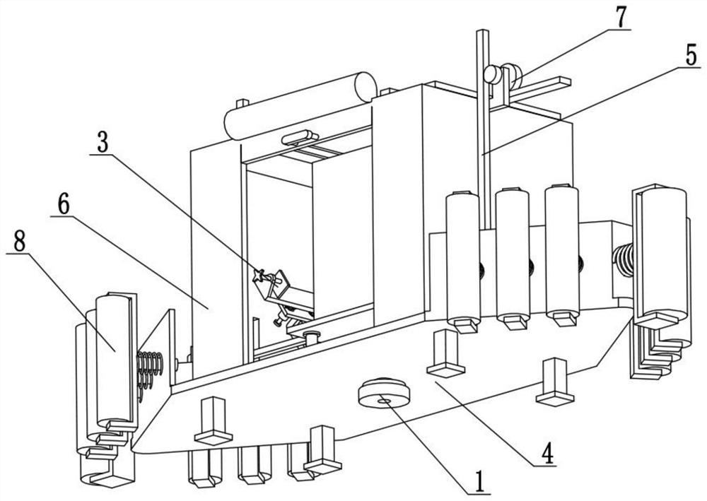
[0028] Combine below Figure 1-10 Describe this embodiment. The present invention relates to the technical field of automobile charging piles, more specifically, new energy automobile charging piles, including a lifting load-bearing mechanism 1, a linkage arm mechanism 2, a clamping and stabilizing mechanism 3, a supporting base mechanism 4, a follow-up Drive mechanism 5, protective cover mechanism 6, follow-up opening and closing mechanism 7 and anti-collision guiding mechanism 8, described two anti-collision guiding mechanisms 8 are respectively connected to the left and right ends of supporting base mechanism 4, and protective cover mechanism 6 is connected on On the support base mechanism 4, the lifting load-bearing mechanism 1 is connected to the support base mechanism 4, and the two linkage arm mechanisms 2 are connected to the lifting load-bearing mechanism 1 and the support base mechanism 4, and the two clamping and stabilizing mechanisms 3 are respectively connected to...

specific Embodiment approach 2

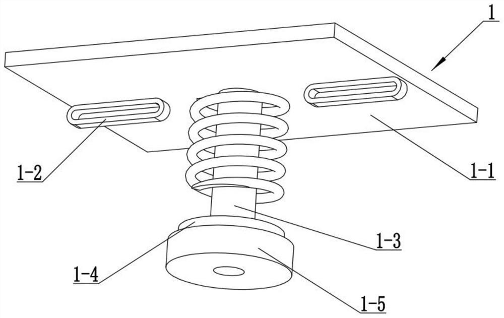
[0031] Combine below Figure 1-10Describe this embodiment, this embodiment will further explain the first embodiment, the lifting load-bearing mechanism 1 includes a load-bearing plate 1-1, a follow-up slide 1-2, a hollow tube 1-3, a circular disc 1- 4 and the annular rubber pad 1-5, the annular rubber pad 1-5 is fixedly connected to the bottom end of the ring disc 1-4, the ring disc 1-4 is fixedly connected to the bottom end of the hollow tube 1-3, and the hollow tube 1-3 is fixedly connected to the bottom end of the load-bearing plate 1-1, and the two follow-up slideways 1-2 are respectively fixedly connected to the left and right ends of the bottom end of the load-bearing plate 1-1.

[0032] Place the charging pile on the load-bearing plate 1-1, and connect the power cord on the charging pile to the power supply through the hollow tube 1-3. When the load-bearing plate 1-1 falls, it will drive the hollow tube 1-3 to drop , the hollow tube 1-3 drives the ring disc 1-4 to pre...

specific Embodiment approach 3

[0034] Combine below Figure 1-10 Describe this embodiment, this embodiment will further explain the second embodiment, the linkage arm mechanism 2 includes a rotating force arm 2-1, a sliding shaft 2-2, a limit plate 2-3 and a sliding sleeve 2-4 , the two sliding sleeves 2-4 are fixedly connected to the limiting plate 2-3, the limiting plate 2-3 is fixedly connected to the limiting plate 2-3, and the bottom end of the limiting plate 2-3 is fixedly connected to the sliding shaft 2-2, the two sliding shafts 2-2 are respectively slidably connected in the two follow-up slideways 1-2.

[0035] When the load-bearing plate 1-1 descends, it will drive the two accompanying slideways 1-2 to descend together, while the two sliding shafts 2-2 will slide in the two accompanying slideways 1-2 respectively, and the two rotating forces will simultaneously The arm 2-1 rotates on the two rotating seats 4-4, so that the two rotating force arms 2-1 rotate to the middle at the same time, so as t...


PUM


Abstract

The invention relates to the technical field of automobile charging piles, in particular to a new energy automobile charging pile. Old, damaged or different voltage levels of charging piles can be replaced by quick disassembly; the charging pile comprises a lifting bearing mechanism, a linkage rotating arm mechanism, a clamping stabilizing mechanism, a supporting base mechanism, a follow-up driving mechanism, a protective cover mechanism, a follow-up opening and closing mechanism and an anti-collision guide mechanism, a bearing plate is pressed to move downwards through the weight of the charging pile, and two rotating force arms are driven to rotate in the downward moving process of the bearing plate; the left end and the right end of the charging pile are clamped and fixed through the two left clamping plates and the two right clamping plates, meanwhile, the four front clamping plates and the four rear clamping plates clamp and fix the four corners of the charging pile in the front-back direction, accidental sliding of the charging pile on the bearing plate is avoided, and meanwhile bolts or other fasteners do not need to be used for fixing the charging pile.

Description

technical field [0001] The invention relates to the technical field of automobile charging piles, more specifically, a new energy automobile charging pile. Background technique [0002] The function of the charging pile is similar to the refueling machine in the gas station. It can be fixed on the ground or wall, and installed in public buildings (public buildings, shopping malls, public parking lots, etc.) and residential area parking lots or charging stations. Charging various types of electric vehicles; however, existing charging piles have different voltage levels and can only charge a single type of vehicle, and a single charging pile is installed in public buildings (public buildings, shopping malls, public parking lots, etc.) It is not easy to disassemble when replacing in the parking lot or charging station of the residential area, which will bring a lot of workload and more working time to the replacement of old, damaged or different voltage level charging piles. ...

Claims


Application Information

Patent Timeline
Patent Type & Authority Applications(China)
IPC IPC(8): B60L53/31
CPCB60L53/31Y02T10/70Y02T10/7072Y02T90/12
Inventor 张杰
Owner 张杰
Why Eureka
Try Eureka