Vehicle anti-creeping energy absorption device

An energy-absorbing device, anti-climbing technology, applied in railway vehicle wheel guards/buffers, transportation and packaging, railway car body parts, etc., can solve deformation, sometimes starting from the rear end, sometimes starting from the middle of the structure, The structure energy absorption sequence is difficult to control, waste and other problems

Active Publication Date: 2021-01-22
SOUTHWEST JIAOTONG UNIV
View PDF9 Cites 0 Cited by
  • Summary
  • Abstract
  • Description
  • Claims
  • Application Information

AI Technical Summary

Problems solved by technology

When the train collides at low speed, the collision kinetic energy is low at this time, but the traditional anti-climbing energy-absorbing device at the end of the car will trigger, and the structure will produce irreversible plastic deformation. The compression deformation displacement of the energy-absorbing structure is very small, but the anti-climbing energy-absorbing The energy device must be replaced again, causing a very large waste and increasing the maintenance cost
In addition, traditional anti-climbing energy-absorbing devices mainly absorb energy through plastic deformation of the structure. For thin-walled collapsed pipes with ribs arranged at equal intervals, the energy-absorbing sequence of the structure is difficult to control. It is expected that the structure will deform from the front end during design. , gradually compressing backwards; but in reality, the position where the structure first deforms has a certain probability, sometimes starting from the front end, sometimes starting from the rear end, and sometimes starting from the middle of the structure
The uncertainty of the initial deformation position of the anti-climbing energy-absorbing structure leads to the instability of the energy-absorbing effect, which affects the crashworthiness of the vehicle and even the train

Method used


Image

  • Vehicle anti-creeping energy absorption device
  • Vehicle anti-creeping energy absorption device
  • Vehicle anti-creeping energy absorption device

Examples


Embodiment Construction

[0026] The technical solutions in the embodiments of the present invention will be clearly and completely described below in conjunction with the accompanying drawings in the embodiments of the present invention. Unless otherwise specified, the relative arrangements and numerical expressions of the components and steps set forth in these embodiments and numerical values ​​do not limit the scope of the invention. At the same time, it should be understood that, for the convenience of description, the sizes of the various parts shown in the drawings are not drawn according to the actual proportional relationship. Techniques, methods and devices known to those of ordinary skill in the relevant art may not be discussed in detail, but where appropriate, such techniques, methods and devices should be considered part of the Authorized Specification. In all examples shown and discussed herein, any specific values ​​should be construed as exemplary only, and not as limitations. Therefo...


PUM


Abstract

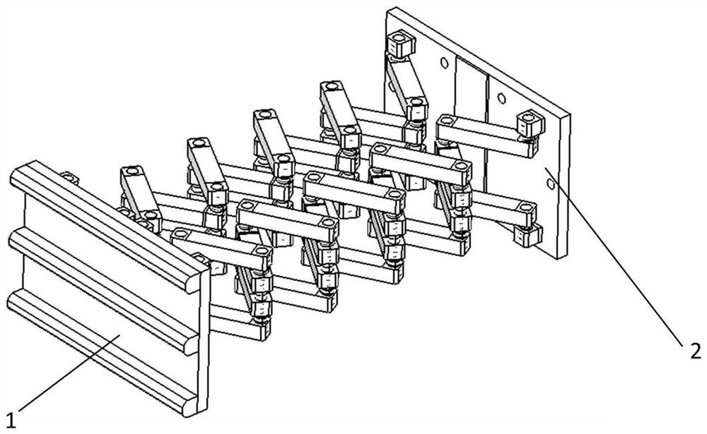
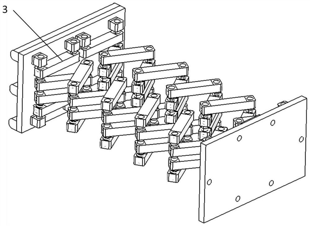
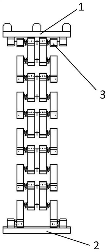
The invention provides a hinge spring type vehicle anti-creeping energy absorption device. The device is mainly composed of a front end anti-creeping structure, a rear end installation structure and amiddle hinge type spring energy absorption structure. The middle hinge type spring energy absorption structure is composed of an inner connecting rod, an outer connecting rod, a pin column and a spiral spring, and comprises five hinge type spring energy absorption basic units from top to bottom, and the torsional rigidity of the spiral spring is sequentially increased. When a vehicle collides ata low speed, the spiral spring generates recoverable elastic torsion to store energy, and the anti-creeping energy absorption device is not damaged; when a vehicle collides at a high speed, the spiralspring generates unrecoverable plastic deformation to absorb energy; and the rigidity of the spiral spring controls the deformation sequence of the energy absorption structure, and the five hinge type spring energy absorption basic units deform in sequence from top to bottom. According to the invention, the technical problems of serious waste, high maintenance cost and unstable energy absorptionsequence of the traditional energy absorption structure for low-speed collision of the railway vehicle can be effectively solved, and the collision resistance of the railway vehicle can be effectivelyimproved.

Description

technical field [0001] The invention relates to the technical field of rail vehicle collision passive safety. Background technique [0002] The crashworthiness of rail vehicles is very important to protect the safety of drivers, passengers and property. The improvement of train speed is an important symbol of the rapid development of rail vehicles, but at the same time it brings another problem. Once a collision accident occurs in a high-speed train, the consequences will be disastrous. Active safety protection measures cannot completely eliminate the occurrence of train collision accidents. Therefore, as the last barrier to protect the safety of drivers and passengers, the passive collision safety performance of rail vehicles is particularly important. [0003] The crashworthiness of a rail vehicle depends primarily on energy-absorbing structures or energy-absorbing elements arranged at the ends of the vehicle. The traditional anti-climbing energy-absorbing device at the ...

Claims


Application Information

Patent Timeline
Patent Type & Authority Applications(China)
IPC IPC(8): B61F19/04
CPCB61F19/04
Inventor 刘艳文肖守讷杨冰朱涛阳光武修瑞仙
Owner SOUTHWEST JIAOTONG UNIV
Why Eureka
Try Eureka