
Anodizing hanger for aluminum profile

A technology for anodizing hangers and aluminum profiles, applied in the field of hangers, which can solve problems such as deformation, increased production costs, and inability to disassemble, and achieve the effect of reducing collision damage

Pending Publication Date: 2021-01-22
ANHUI JINYING ALUMINUM
View PDF3 Cites 0 Cited by
  • Summary
  • Abstract
  • Description
  • Claims
  • Application Information

AI Technical Summary

Problems solved by technology

The parts in the existing hangers are usually welded and fixed together, which cannot be disassembled, and are easily deformed and damaged by collisions during the use of the hanger, especially when the hanging teeth on the hanger are damaged, it will affect each The number of workpieces that can be mounted on the hanger will reduce the production efficiency. At present, when the loss of the hanger on the hanger exceeds 10% of the total, it must be repaired, and the maintenance of the hanger is time-consuming and difficult. It will also affect production efficiency. On the other hand, because the cycle of anodized products is usually short, the types and shapes of workpieces are changed frequently. For different workpieces, the shape of the corresponding hanging teeth and the spacing between the hanging teeth need to be changed. It is more difficult to transform the hanger, so in most cases, different hangers can only be manufactured for different types of workpieces. For products that are no longer produced, the corresponding hangers can only be scrapped and sold as scrap metal. Most of the material of the hanger is titanium metal, especially the main frame body, the price is high, so it will increase the production cost. Most of the hangers are easy to fall off when they are dumped or swung during use, and it is not easy to remove after being fixed. use

Method used


Image

  • Anodizing hanger for aluminum profile
  • Anodizing hanger for aluminum profile
  • Anodizing hanger for aluminum profile

Examples


Embodiment Construction

[0016] The technical solutions in the embodiments of the present invention will be clearly and completely described below with reference to the accompanying drawings in the embodiments of the present invention. Obviously, the described embodiments are only a part of the embodiments of the present invention, but not all of the embodiments. Based on the embodiments of the present invention, all other embodiments obtained by those of ordinary skill in the art without creative efforts shall fall within the protection scope of the present invention.

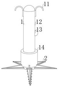
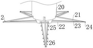
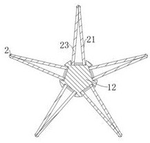
[0017] see Figure 1-4 , the present invention provides a technical solution: an anodized hanger for aluminum profiles, including a hanging rod assembly 1, the hanging rod assembly 1 includes a fixing hook 11, a hanging rod 12 and a shrink ring 14, and the two sides of the hanging rod 12 are fixed symmetrically. The fixed hook 11 placed, the outer wall of the hanging rod 12 is slidably connected to the shrinking ring 14 in a coaxial l...


PUM


Abstract

The invention discloses an anodizing hanger for an aluminum profile. The anodizing hanger comprises a hanging rod assembly, the hanging rod assembly comprises fixing hooks, a hanging rod and a contraction ring, the two sides of the hanging rod are fixedly connected with the fixing hooks which are symmetrically arranged, the outer wall of the hanging rod is coaxially and slidably connected with thecontraction ring, and a retracting and releasing assembly is arranged on the bottom end face of the contraction ring. The retracting and releasing assembly comprises a contraction rod, contraction grooves, a placing rod I, a placing rod II, rotating pins, a supporting groove and a hanging piece mechanism, the bottom end face of the contraction ring circumferentially and evenly penetrates throughthe five contraction grooves, the interiors of the contraction grooves are rotationally connected with one end of the contraction rod through pins, and the other end of the contraction rod is insertedand connected between the placing rod II and the placing rod I. The placing rod II, the placing rod I and the contraction rod are rotationally connected through the rotating pins, the placing rod IIand the placing rod I are rotationally connected into the supporting groove through pins, the bottom end faces of the placing rod II and the placing rod I are connected with the hanging piece mechanism through threads, and a plurality of aluminum profile pieces are clamped to the hanging piece mechanism.

Description

technical field [0001] The invention relates to the technical field of hangers, in particular to an anodized hanger for aluminum profiles. Background technique [0002] In the anodizing process, the workpiece needs to be installed on the hanger, and then the hanger is passed through each processing tank or processing device in turn by the conveying device to carry out the processing operation. The components in the existing hangers are usually welded and fixed together and cannot be disassembled. In the use of the hangers, they are easily deformed and damaged due to collisions, especially when the hanging teeth on the hangers are damaged. The number of workpieces that can be mounted on the hanger will reduce the production efficiency. At present, usually when the loss of the hanger on the hanger exceeds 10% of the total, it must be repaired, and the maintenance of the hanger is time-consuming and difficult. It will also affect the production efficiency. On the other hand, b...

Claims


Application Information

Patent Timeline
IPC IPC(8): C25D11/04C25D17/08
CPCC25D11/04C25D17/08Y02E10/50
Inventor 宋彬彬孙海阔王少博
Owner ANHUI JINYING ALUMINUM
Learn More