Rapid mounting auxiliary device for street lamp

An auxiliary and fast technology for installation, which is applied in the field of quick installation auxiliary devices for street lamps, and can solve problems such as inability to install street lamp poles

Inactive Publication Date: 2021-01-22
扬州市泰元照明工程有限公司
View PDF8 Cites 2 Cited by
  • Summary
  • Abstract
  • Description
  • Claims
  • Application Information

AI Technical Summary

Problems solved by technology

[0005] In view of the above situation, in order to overcome the defects of the prior art, the present invention provides a quick installation auxiliary device for street lamps, which effectively solves the problem that the auxiliary installation device for street lamps in the above background technology cannot independently install street lamp poles and needs lifting equipment. The problem of assisting to use effectively

Method used


Image

  • Rapid mounting auxiliary device for street lamp
  • Rapid mounting auxiliary device for street lamp
  • Rapid mounting auxiliary device for street lamp

Examples


Embodiment 1

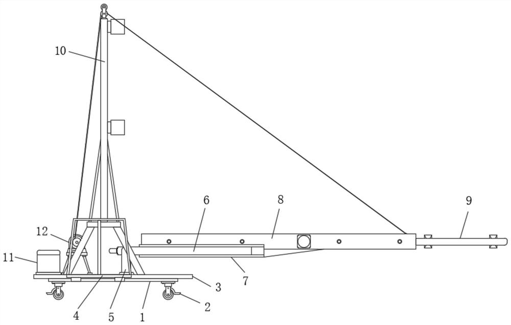
[0031] Embodiment one, by Figure 1 to Figure 5Given, the present invention includes a U-shaped underframe 1, and moving wheels 2 are installed on both ends of the bottom of the U-shaped underframe 1 and both sides of the middle of the bottom. By setting the moving wheels 2, the device can be effectively moved, and The moving wheel 2 is a mobile brake wheel, and the top of the U-shaped underframe 1 is fixedly equipped with a base plate 3, and a bearing platform 4 is installed between the two sides of the base plate 3 and the two sides of the U-shaped underframe 1, and the two sides of the base plate 3 top Both sides are fixedly equipped with fixed columns 5, and the tops of the opposite sides of the two fixed columns 5 are equipped with rotating arms 6, and the opposite sides of the two rotating arms 6 are equipped with U-shaped connecting moving plates 7, and the two U-shaped connecting moving plates The opposite sides of 7 are all fixedly installed with L-shaped fixed plates...

Embodiment 2

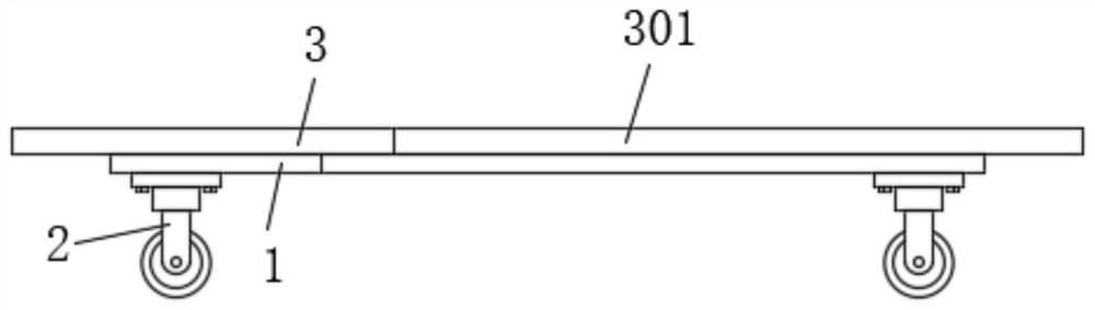
[0032] Embodiment two, on the basis of embodiment one, by figure 2 Given, an installation alignment groove 301 is opened in the middle of one end of the bottom plate 3, so that the street light poles can be aligned and installed effectively.

Embodiment 3

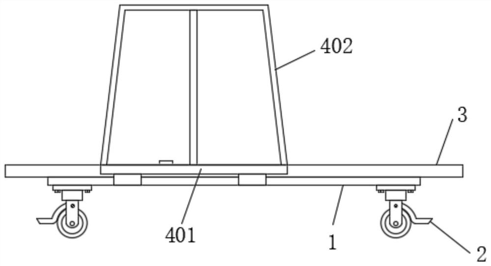
[0033] Embodiment three, on the basis of embodiment one, by image 3 Given, the two carrying platforms 4 all include a carrying plate 401 and a guardrail 402, the two carrying plates 401 are fixedly installed on both sides of the bottom plate 3 respectively, the guardrail 402 is fixedly installed on one side of the bottom of the carrying plate 401, and the bottom of the carrying plate 401 Both sides and the U-shaped bottom frame 1 are fixedly installed with fixed connecting blocks, so that the device can be moved effectively, and when the street light pole is clamped and rotated, the gravity of the worker can increase the self-weight of the device to maintain balance.


PUM


Abstract

The invention relates to the technical field of street lamp mounting equipment, and discloses a rapid mounting auxiliary device for a street lamp. The rapid mounting auxiliary device aims to solve theproblems that an existing street lamp mounting auxiliary device cannot independently mount a street lamp post and only can be effectively used under the assistance of hoisting equipment. The rapid mounting auxiliary device comprises a U-shaped bottom frame, moving wheels are installed at the two ends of the bottom and the two sides of the middle of the bottom of the U-shaped bottom frame, a bottom plate is fixedly installed at the top of the U-shaped bottom frame, bearing tables are installed between the two sides of the bottom plate and the two sides of the U-shaped bottom frame, fixing columns are fixedly installed on the two sides of the top of the bottom plate, rotating arms are installed at the tops of the opposite sides of the two fixing columns, and U-shaped connecting moving plates are installed on the opposite sides of the two rotating arms. The rapid mounting auxiliary device for the street lamp can effectively fix the street lamp pole placed on the ground, can rotate the street lamp pole and keep the street lamp pole in a vertical state, and meanwhile can stably move, adjust and install the fixed street lamp pole.

Description

technical field [0001] The invention belongs to the technical field of street lamp installation equipment, in particular to a quick installation auxiliary device for street lamps. Background technique [0002] Street lights are lamps installed on the roadside to provide light for the road at night. Most of the existing street lights are pole street lights, and there are many types, including high pole street lights, road lights, monitoring poles, new special-shaped tube street lights, stainless steel landscape lights, Shaped landscape lights, sculptured landscape lights, garden lights, cast aluminum garden lights, cast iron garden lights, stainless steel garden lights, shaped garden lights, new special-shaped tube garden lights, iron lights, spotlights, lawn lights, stainless steel lawn lights, outdoor wall lights, Firework lights etc. [0003] The patent application with notification number CN207406104U discloses an auxiliary device for horizontal erection and fixing of st...

Claims


Application Information

Patent Timeline
Patent Type & Authority Applications(China)
IPC IPC(8): E04H12/34
CPCE04H12/34E04H12/347
Inventor 周德林陈礼继
Owner 扬州市泰元照明工程有限公司
Why Eureka
Try Eureka