
Horizontal well cementation sliding sleeve partial pressure pipe outer optical fiber system and monitoring method thereof

A technology of optical fiber system and pressure dividing tube, which is applied in the direction of wellbore/well components, earthwork drilling, production fluid, etc. It can solve the problems of inability to evaluate the fracturing effect and obtain the flow information of the fracturing sliding sleeve, etc. fracturing effect, ensuring monitoring reliability, and ensuring the effect of fracturing reliability

Active Publication Date: 2021-01-22
PETROCHINA CO LTD
View PDF16 Cites 1 Cited by
  • Summary
  • Abstract
  • Description
  • Claims
  • Application Information

AI Technical Summary

Problems solved by technology

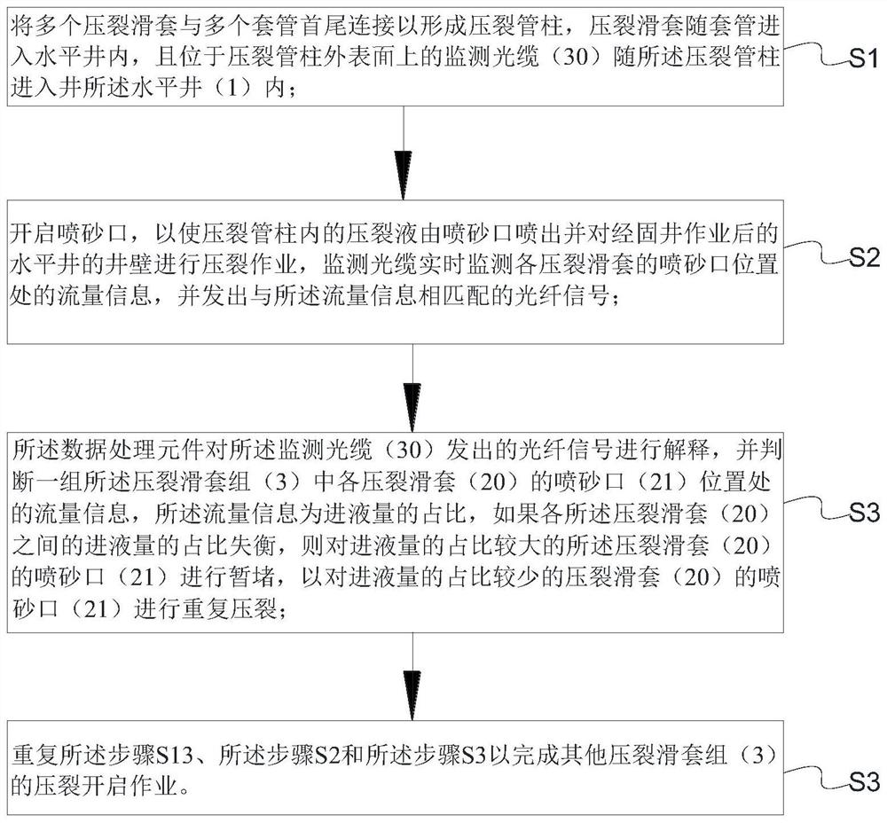
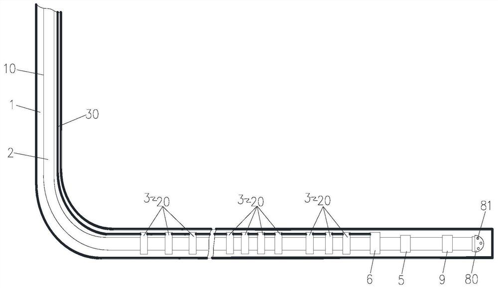
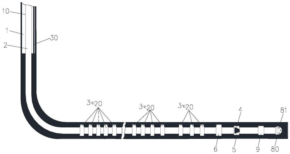
[0003] The main purpose of the present invention is to provide a monitoring method for the optical fiber system outside the pressure dividing pipe of the horizontal well cementing sliding sleeve and its monitoring method, so as to solve the process of subdividing and cutting the horizontal well and volume fracturing in the prior art. In the process, the flow information at the sandblasting port of the fracturing sleeve cannot be obtained, and the fracturing effect cannot be evaluated

Method used


Image

  • Horizontal well cementation sliding sleeve partial pressure pipe outer optical fiber system and monitoring method thereof
  • Horizontal well cementation sliding sleeve partial pressure pipe outer optical fiber system and monitoring method thereof
  • Horizontal well cementation sliding sleeve partial pressure pipe outer optical fiber system and monitoring method thereof

Examples


Embodiment Construction

[0033]The following will clearly and completely describe the technical solutions in the embodiments of the present invention with reference to the accompanying drawings in the embodiments of the present invention. Obviously, the described embodiments are only some of the embodiments of the present invention, not all of them. The following description of at least one exemplary embodiment is merely illustrative in nature and in no way taken as limiting the invention, its application or uses. Based on the embodiments of the present invention, all other embodiments obtained by persons of ordinary skill in the art without creative efforts fall within the protection scope of the present invention.

[0034] In order to solve the problems in the prior art that the flow information at the sandblasting port of the fracturing sleeve cannot be obtained and the fracturing effect cannot be evaluated during the staged fracturing operation of the horizontal well, the present invention provides...


PUM


Abstract

The invention provides a horizontal well cementation sliding sleeve partial pressure pipe outer optical fiber system and a monitoring method thereof. The horizontal well cementation sliding sleeve partial pressure pipe outer optical fiber system comprises a plurality of casing pipes, a plurality of fracturing sliding sleeves and a monitoring optical cable, the casing pipes are connected with the fracturing sliding sleeves, the multiple casing pipes and the multiple fracturing sliding sleeves are connected end to end to form a fracturing string, the fracturing sliding sleeves are provided withsand blasting openings, the sand blasting openings are opened so that fracturing fluid in the fracturing string is sprayed out from the sand blasting openings, and fracturing operation is conducted ona target reservoir of a horizontal well after well cementation operation. The monitoring optical cable is arranged on the outer surface of the fracturing string so as to enter the horizontal well along with the fracturing string and monitor flow information at the position of the sand blasting opening of each fracturing sliding sleeve in real time. The problems that in the prior art, in the process of conducting subdivision cutting and volume fracturing operation on a horizontal well, flow information at the position of a sand blasting opening of a fracturing sliding sleeve cannot be obtained, and the fracturing effect cannot be evaluated are solved.

Description

technical field [0001] The invention relates to the field of oil and gas field development downhole fracturing pipe strings and testing technologies, in particular to an optical fiber system outside a horizontal well cementing sliding sleeve pressure dividing pipe and a monitoring method thereof. Background technique [0002] In the prior art, during the subdivision cutting and volume fracturing operation of horizontal wells, the flow information at the sandblasting ports of the fracturing sliding sleeves in each section and cluster of the staged fracturing device cannot be obtained, resulting in The operator cannot accurately obtain the opening information of the sandblasting port, and even cannot obtain the output information of the sandblasting port in the subsequent production stage. Contents of the invention [0003] The main purpose of the present invention is to provide a monitoring method for the optical fiber system outside the pressure dividing pipe of the horizo...

Claims


Application Information

Patent Timeline
Patent Type & Authority Applications(China)
IPC IPC(8): E21B43/26E21B43/114E21B33/13E21B47/135
CPCE21B43/26E21B43/114E21B43/261Y02E10/10
Inventor 谢斌董小卫田志华潘勇刘海龙舒博钊韩光耀王宁博汪志刘帅
Owner PETROCHINA CO LTD
Learn More