
Valve element structure, faucet and driving system

A faucet and valve core technology, applied in the field of the faucet valve core, can solve the problems of difficulty in promotion, increase the volume of the water inlet, complex structure, etc., and achieve the effect of solving the shortcomings of cold water serial flow, increasing the flow rate per unit time, and overcoming the problem of narrow channels.

Active Publication Date: 2021-01-22
陈宗仁
View PDF7 Cites 0 Cited by
  • Summary
  • Abstract
  • Description
  • Claims
  • Application Information

AI Technical Summary

Problems solved by technology

[0006] The shaft of the impeller passes through the wall of the water pipe. Due to the high pressure of the tap water, it is necessary to keep the shaft rotating while sealing. The manufacturing process and cost are high.
[0007] Another example is that the application number 201621373294.3 discloses the anti-channeling structure installed on the double water inlets. It is difficult to popularize the interface of domestic tap water pipes; this structure is that the double water inlets are equipped with one-way valves, and the two water inlet channels cannot be connected.

Method used


Image

  • Valve element structure, faucet and driving system
  • Valve element structure, faucet and driving system
  • Valve element structure, faucet and driving system

Examples


Embodiment 1

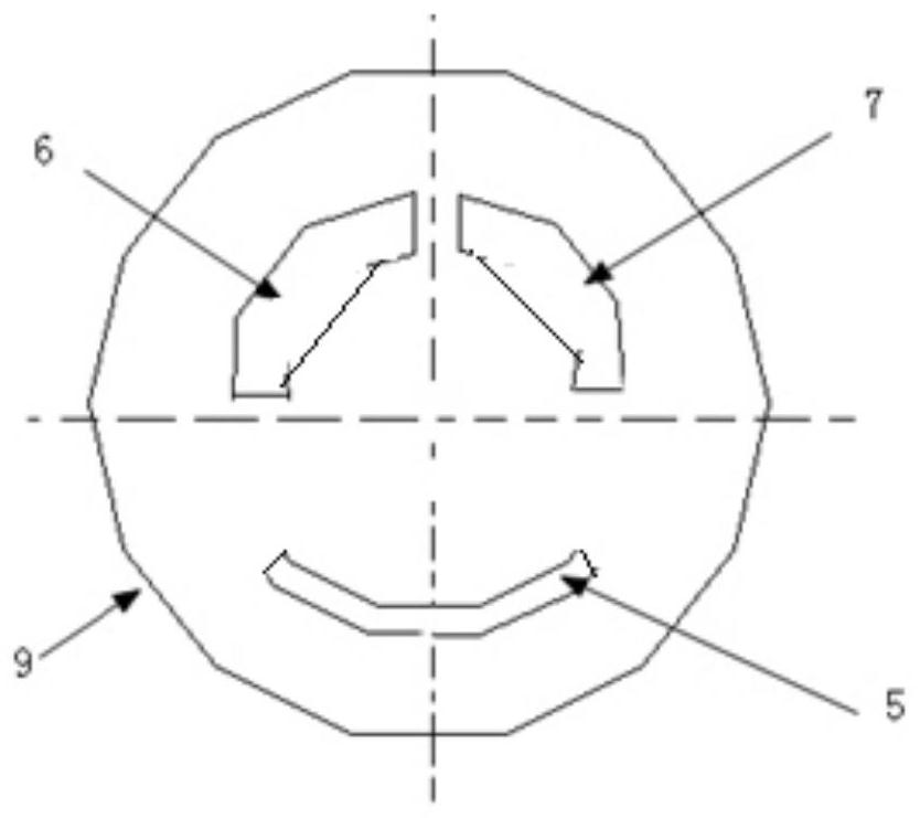
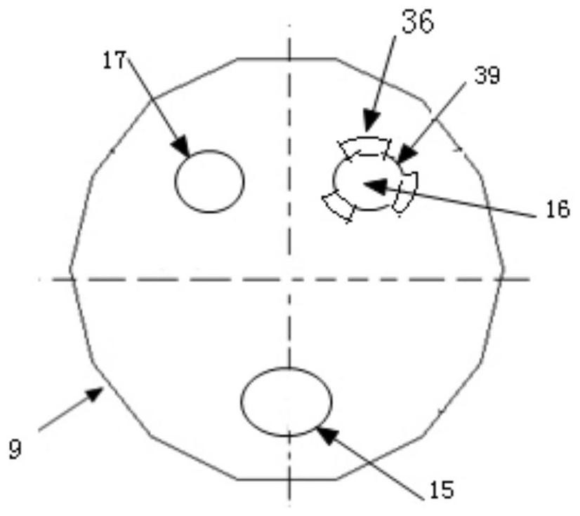
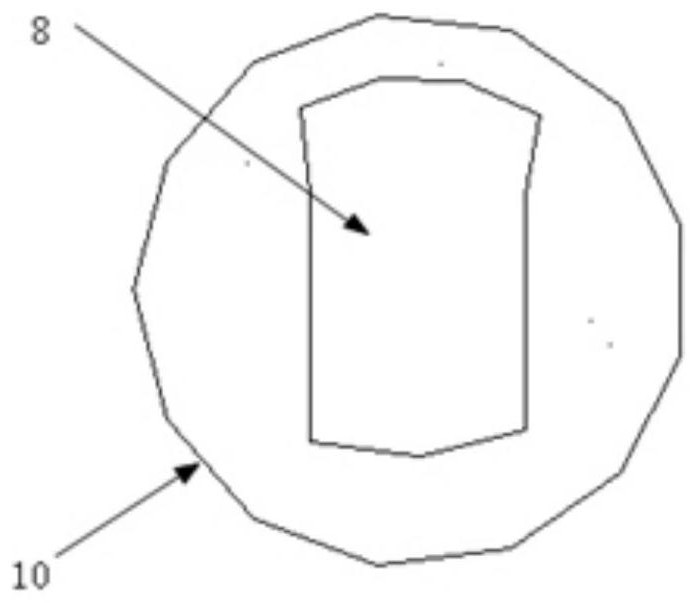
[0088] Spool 2 is in Figure 5 Position: tap water enters the water heater 14 from the tap water interface 28 and the second water pipe 19, hot water enters the first water pipe 18 from the water outlet port 25, extends through the water pipe to the first water inlet 11 of the faucet, and flows through the internal passage 41 of the body 3 to the first Water inlet outer hole 33. The water flow breaks away the sealing surface 34 of the sealing cap 4, and reaches the first water inlet 16 of the fixed part 9 of the valve core 2 along the diversion groove 35 and the diversion groove 39, and communicates with the second water inlet through the groove 8 of the rotating part 10 17. The second water inlet hole 17 is connected to the second water inlet outer hole 44, passes through the second water inlet 12 of the faucet, and then enters the second water pipe 19. The water flow flows along the hot water outlet direction, forming a water flow loop. The water flow is unidirectionally com...

Embodiment 2

[0091] Faucet 27 handle 1 is in such as Figure 4 position, when hot and cold mixed water flows out or only hot water flows out when turning the handle 1 at this position, the control circuit 24 receives the hot water signal from the Hall sensor 22, and then collects the first temperature sensor 20 and the second temperature sensor 21 water temperature signal. Turn the handle 1 as Figure 5 The groove 8 is connected to the first water inlet tank 6 and the second water inlet tank 7 at the right position, the water circuit forms a closed passage, the water pump 23 is started to work, and the water flow is driven to circulate, and the hot water in the water heater 14 enters the first water pipe 18 from the water outlet port 25 to the faucet The first water inlet 11. The water flows through the internal channel 41 of the body 3 to the first water inlet outer hole 33, enters the first water inlet hole 16 of the fixing part 9 through the one-way valve, communicates with the second...

Embodiment 3

[0095] The Hall sensor 22 starts the water pump to work when the water flow per unit time is less than the set value. Pressurizes the water stream to increase flow and improve shower comfort.


PUM


Abstract

The invention discloses a valve element structure, a faucet and a driving system. The valve element structure comprises a rotating part, a fixing part and a bottom plate; the fixing part and the bottom plate are stacked up and down with two water inlets and a water outlet formed, the water inlets and the water outlet penetrate through the fixing part and the bottom plate, and a one-way valve is arranged at one water inlet; the rotating part is located on the side, away from the bottom plate, of the fixing part; a groove capable of making the two water inlets communicated and the water outlet closed is formed in the rotating part; and the one-way valve is used for achieving one-way communication of the two water inlets. A spring and a sealing cap of the one-way valve are arranged in the corresponding water inlet of the valve element, the cost is low, a waterway flows unidirectionally in the hot water outflow direction, and the defect of cold water mixing is overcome.

Description

technical field [0001] The invention relates to the technical field of faucet valve cores, in particular to a valve core structure with a one-way channel, a water faucet including the valve core structure and a driving system including the water faucet. Background technique [0002] Existing zero-cold water external circulation systems for water heaters, such as application number 202010176653.0 spool, faucet, and circuit fluid supply system with the faucet, discloses an external zero-cold water water heater water circulation system, involving valve cores, faucets, and circuit fluid supply systems . [0003] There is a technical defect that the water circuit connected to the faucet is a two-way flow. When hot water is used at multiple hot water outlets, cold water will flow out from the hot water outlet through the internal channel of the mixed water faucet. [0004] The fluid supply device is only installed separately at the water inlet or outlet of the water heater, and c...

Claims


Application Information

Patent Timeline
Patent Type & Authority Applications(China)
IPC IPC(8): F16K11/074F16K3/314F16K27/04F16K37/00F24H9/20
CPCF16K11/074F16K3/314F16K27/045F16K37/0091F24H9/20
Inventor 陈宗仁
Owner 陈宗仁
Learn More