
Automobile axle distance measuring method

A measurement method and technology for automobile axles, which are used in vehicle testing, measurement devices, radio wave measurement systems, etc., can solve the problems of complex installation process, inaccurate measurement, slow passing, etc., and achieve accurate measurement results, direct judgment and output. , The measurement process is convenient and efficient

Pending Publication Date: 2021-01-22
成都新成汽车检测设备有限公司
View PDF0 Cites 5 Cited by
  • Summary
  • Abstract
  • Description
  • Claims
  • Application Information

AI Technical Summary

Problems solved by technology

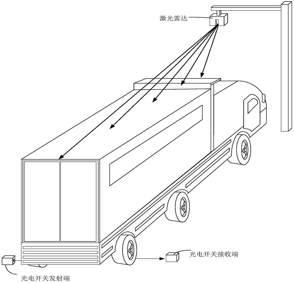
[0003] The schematic diagram of measuring the wheelbase of a car using a laser radar combined with a photoelectric switch is as follows figure 1 As shown, the car slowly passes through the measurement area. During the driving process of the car, the laser radar will locate the car. When the tires of the car block the photoelectric switch, the photoelectric switch will make a record. The positioning data of the vehicle and the data recorded by the photoelectric switch are used to calculate the wheelbase of the car under test. However, in this method, when other parts of the car block the photoelectric switch, the photoelectric switch will also record the corresponding data, resulting in inaccurate measurement
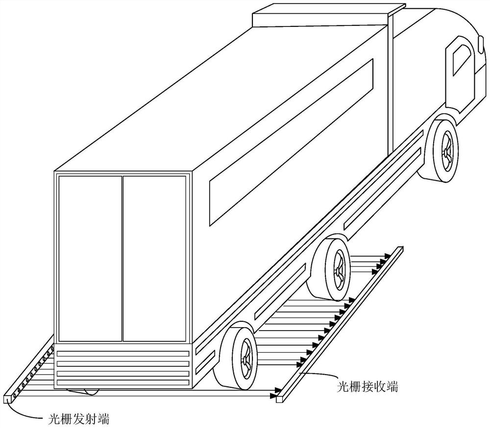
[0004] The schematic diagram of measuring the wheelbase of a car using a grating is as follows figure 2 As shown, the grating is a measuring device that integrates multiple groups of parallel lasers. This measurement method requires that the installation length of the grating be at least greater than the longest wheelbase of the car to be tested. Gratings, problems that lead to inaccurate measurements

Method used


Image

  • Automobile axle distance measuring method
  • Automobile axle distance measuring method
  • Automobile axle distance measuring method

Examples


Embodiment Construction

[0031] The following describes the embodiments of the present invention in detail. In the description of the present invention, it should be understood that when it comes to orientation descriptions, for example, the orientations or positional relationships indicated by up, down, front, back, left, and right are based on the accompanying drawings. The orientation or positional relationship shown is only for the convenience of describing the present invention and simplifying the description, but does not indicate or imply that the device or element referred to must have a specific orientation, be constructed and operated in a specific orientation, and therefore cannot be construed as limiting the scope of the present invention. limit.

[0032] In the description of the present invention, if the first and the second are described only for the purpose of distinguishing technical features, it cannot be understood as indicating or implying relative importance or implicitly indicatin...


PUM


Abstract

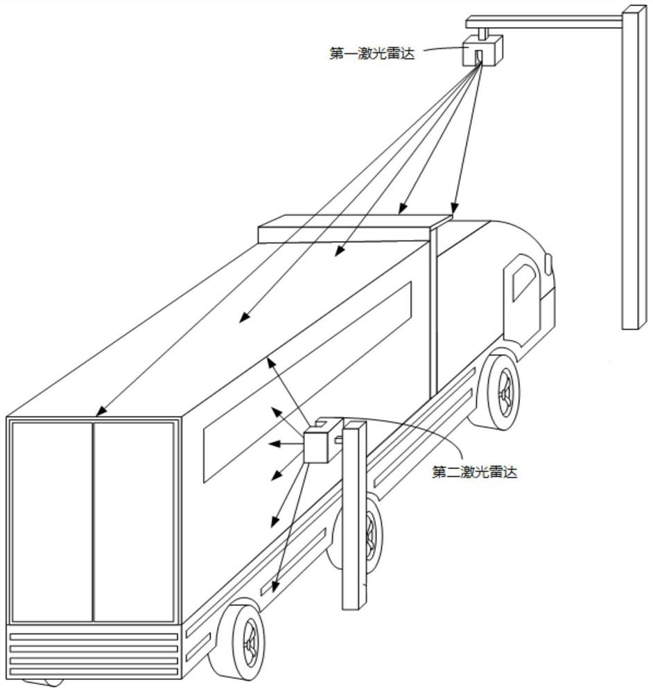
The invention relates to the technical field of automobile detection, and discloses an automobile axle distance measuring method. The method adopts non-contact measurement, and comprises the followingsteps of scanning the head of an automobile by using a first laser radar and scanning the side body of the automobile by using a second laser radar in an automobile advancing process; and combining data measured by the first laser radar and data measured by the second laser radar to obtain three-dimensional coordinate data of the automobile, converting the three-dimensional coordinate data to obtain a two-dimensional graph of the side surface of an automobile tire, finally processing a two-dimensional graph to obtain the position and a contour of the automobile tire, and calculating to acquire the axle distance of the automobile. The measurement process is more convenient and efficient, the measurement result is not affected by other parts of the automobile, the measurement result is moreaccurate, direct judgment and output can be achieved, and the method can be suitable for vehicles of various brands and models.

Description

technical field [0001] The invention relates to the technical field of automobile detection, in particular to a method for measuring the wheelbase of automobiles. Background technique [0002] When the car is undergoing registration safety inspection, the wheelbase of the car should be consistent with its product announcement and factory certificate, and the error should not exceed ±1% or ±50mm, so the wheelbase of the car needs to be measured. In the prior art, there are mainly two methods for measuring the wheelbase of a vehicle: one is to use a laser radar combined with a photoelectric switch for measurement, and the other is to use a grating for measurement. [0003] The schematic diagram of measuring the wheelbase of a car using a laser radar combined with a photoelectric switch is as follows figure 1 As shown, the car slowly passes through the measurement area. During the driving process of the car, the laser radar will locate the car. When the tires of the car block ...

Claims


Application Information

Patent Timeline
IPC IPC(8): G01S17/89G01M17/007
CPCG01S17/89G01M17/007
Inventor 周建秦光华周维江
Owner 成都新成汽车检测设备有限公司
Learn More