
Filament diameter detection device and method

A detection method and detection device technology, applied in the direction of measuring devices, optical devices, instruments, etc., can solve the problems of high measurement intensity, inconvenient measurement, and inability to measure online, and achieve simple system devices, convenient operation, and stable measurement results Effect

Active Publication Date: 2017-12-01
SUZHOU JIANGAO OPTOELECTRONICS TECH
View PDF4 Cites 0 Cited by
  • Summary
  • Abstract
  • Description
  • Claims
  • Application Information

AI Technical Summary

Problems solved by technology

Contact measurement methods mainly include caliper method, micrometer measurement method, ruler method, bow height method and coordinate measuring machine measurement method. Although contact measurement method is widely used, it is easy to cause damage to the surface of the tested part damage, and cannot be measured online, and the measurement efficiency is low
Non-contact measurement methods mainly include weighing method, photoelectric measurement method and microscope measurement method; the weighing method can only measure the average diameter of the filament, and cannot determine the exact size of each position of the filament; the photoelectric measurement method mainly includes Projection method, interferometry and diffraction method, they all have the disadvantages of inconvenient measurement and instability
Traditional microscopes use visual reading, which has low efficiency and high measurement intensity, and human factors are greatly affected during measurement, resulting in unstable measurement results

Method used


Image

  • Filament diameter detection device and method
  • Filament diameter detection device and method

Examples


Embodiment Construction

[0026] The present invention will be specifically introduced below in conjunction with the accompanying drawings and specific embodiments.

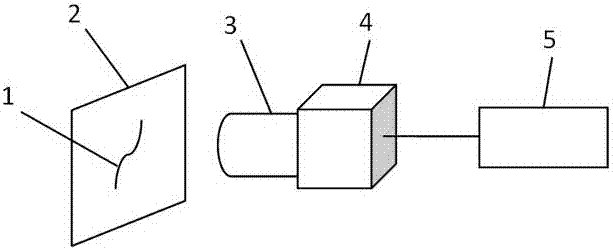
[0027] Such as figure 1 The shown filament diameter detection device includes: a liquid crystal display 2, a microscopic imaging system 3, an image sensor 4, and an image processing system 5; the microscopic imaging system 3 is aligned with the liquid crystal display 2, the microscopic imaging system 3 and the image sensor 4 connected, the image sensor 4 transmits the image formed by the microscope imaging system to the image processing system 5 .

[0028] The liquid crystal display 2 is perpendicular to the optical axis of the microscopic imaging system 3 , so that each pixel of the liquid crystal display 2 is evenly distributed in the field of view of the microscopic imaging system 3 .

[0029] The microscopic imaging system 3 is an optical system, which is a photoelectric imaging system composed of optical elements, and the objective ...


PUM


Abstract

The invention discloses a filament diameter detection device, comprising: a liquid crystal display, a micro imaging system, an image sensor, and an image processing system; the micro imaging system is aligned with the liquid crystal display, the micro imaging system is connected with the image sensor, and the image sensor will The image formed by the microscope imaging system is transmitted to the image processing system. The filament diameter detection method of the present invention includes the following steps: 1) calculating the image pixel distance between each liquid crystal pixel on the liquid crystal display; 2) calculating the image in the image according to the actual pixel spacing of the liquid crystal display The ratio of the pixel distance to the actual distance; 3) Calculate the pixel diameter of the filament in the liquid crystal display; 4) Calculate the actual diameter of the filament according to the ratio obtained in step 2). The invention is beneficial in that the uniformity and accuracy of each pixel point in the liquid crystal display are fully utilized, the diameter of the filament is measured in a non-contact manner, and the system device is simple and easy to operate.

Description

technical field [0001] The invention relates to a test method and device, in particular to a liquid crystal display-based filament diameter detection device and method. Background technique [0002] With the improvement of modern manufacturing technology, the individual pixels of LCD can be made smaller and smaller, and the uniformity of pixels can reach a very precise level. In addition to promoting the rapid development of modern display technology, such an excellent characteristic of liquid crystal can also provide a certain space for the development of precision dimension measurement. [0003] The measurement of filament diameter has always been an important research direction in length measurement. The current measurement methods mainly include contact measurement and non-contact measurement. Contact measurement methods mainly include caliper method, micrometer measurement method, ruler method, bow height method and coordinate measuring machine measurement method. Alth...

Claims


Application Information

Patent Timeline
Patent Type & Authority Patents(China)
IPC IPC(8): G01B11/08
Inventor 林斌杨松涛熊义可曹向群
Owner SUZHOU JIANGAO OPTOELECTRONICS TECH
Learn More