A fiber collimator

An optical fiber collimator and optical fiber technology, applied in the field of optical fiber, can solve the problems of high coherence light source interference speckle and so on

Active Publication Date: 2021-07-06
SHANGHAI INST OF OPTICS & FINE MECHANICS CHINESE ACAD OF SCI
View PDF4 Cites 0 Cited by
  • Summary
  • Abstract
  • Description
  • Claims
  • Application Information

AI Technical Summary

Problems solved by technology

The disadvantage of this invention is that it is not suitable for supercontinuum light sources with high coherence. The achromatic lens uses optical glue to paste and fix the surfaces of the two lens parts. Due to the difference in refractive index between the glue layer and the lens, and the The anti-reflection coating usually only has the anti-reflection effect in some wavelength bands, which can easily lead to the formation of interference patterns when the beam of high coherence light sources is collimated

Method used


Image

  • A fiber collimator
  • A fiber collimator
  • A fiber collimator

Examples


Embodiment 1

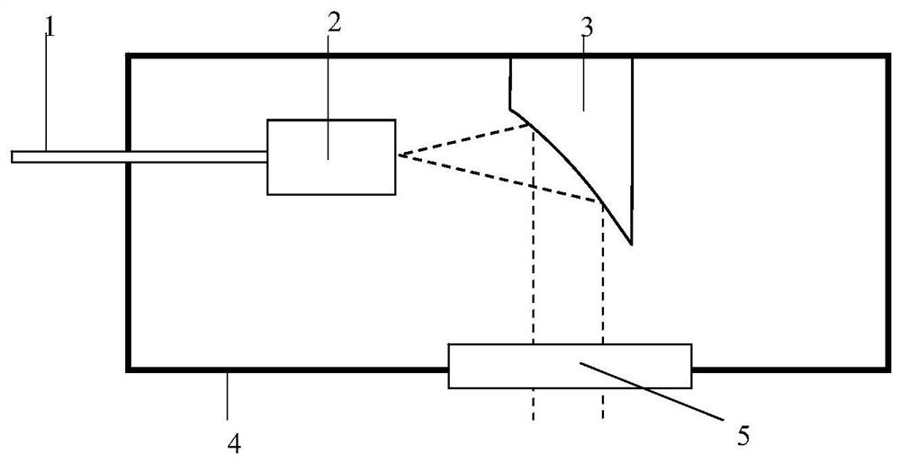
[0045] Such as figure 1 A schematic of the fiber collimator is shown. figure 1 The shown fiber collimator includes a broadband optical fiber 1, an optical fiber end cap 2, an off-axis parabolic reflector 3 and a package module 4, and the broadband optical fiber 1, the fiber end cap 2 and the off-axis parabolic reflector 3 are installed inside the package module 4 , the output port of the fiber end cap 2 is located at the focal point of the off-axis parabolic mirror 3 , and the packaging module 4 is provided with a window mirror 5 , and the window mirror 5 is located on the output optical path of the off-axis parabolic mirror 3 .

[0046] In this embodiment, the broadband optical fiber 1 adopts a photonic crystal fiber with a core diameter of 3 μm, a duty cycle of 0.4, a cladding diameter of 125 μm, and a coating diameter of 250 μm. The fusion splicer is discharged at half the standard intensity until completely collapsed. Cut under a microscope so that the length of the coll...

Embodiment 2

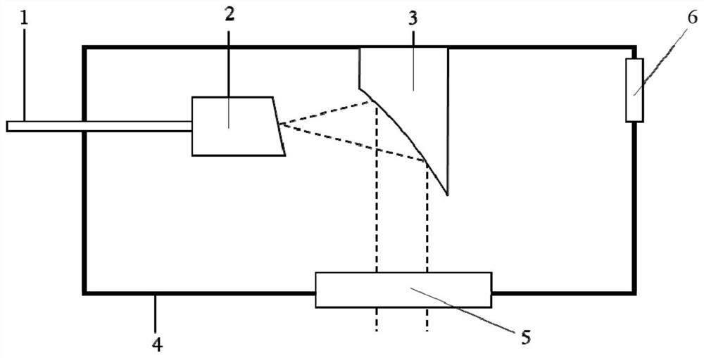
[0048] Such as figure 2 Shown is a schematic diagram of a fiber collimator with gas path inlet and outlet. figure 2 The fiber collimator shown includes a broadband optical fiber 1, an optical fiber end cap 2, an off-axis parabolic reflector 3 and a package module 4, and the broadband optical fiber 1, the fiber end cap 2 and the off-axis parabolic reflector 3 are installed inside the package module 4 , the output port of the fiber end cap 2 is located at the focal position of the off-axis parabolic reflector 3, the package module 4 is provided with a window mirror 5, and the window mirror 5 is located on the output optical path of the off-axis parabola reflector 3, the package module There is also a gas path inlet and outlet interface 6, the gas path inlet and outlet interface 6 has two channels of inlet and outlet, when transmitting a beam of a specific spectral range, a specific gas cycle can be selected to fill the cavity of the packaging module 4, reducing the absorption lo...

Embodiment 3

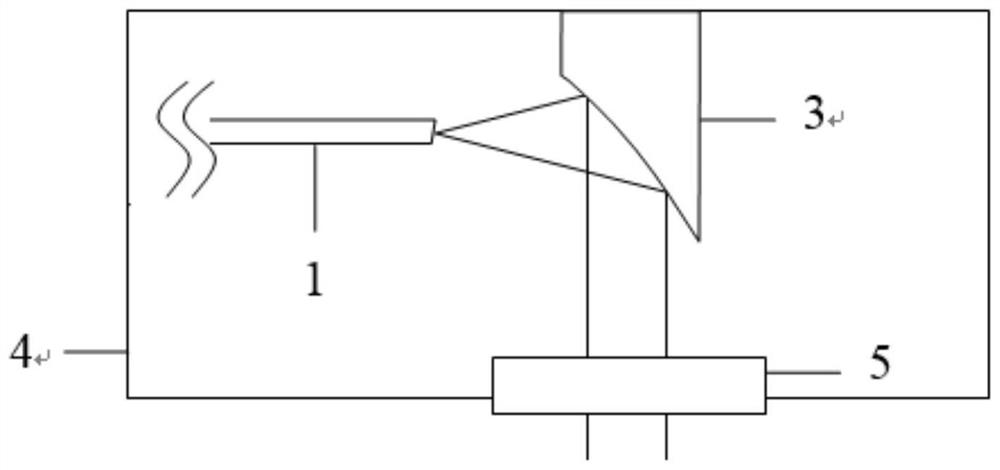
[0051] Such as image 3 A schematic of a fiber collimator without fiber end caps is shown. image 3 The shown fiber collimator comprises a broadband optical fiber 1, an off-axis parabolic mirror 3 and a packaging module 4, the broadband optical fiber 1 and the off-axis parabolic mirror 3 are installed inside the packaging module 4, and the output port of the broadband optical fiber is located off-axis The focus position of the off-axis parabolic reflector 3 , the package module 4 is provided with a window mirror 5 , and the window mirror 5 is located on the output optical path of the off-axis parabolic reflector 3 .

[0052] In this embodiment, the broadband optical fiber 1 is a quartz optical fiber with a core diameter of 25 μm and a cladding diameter of 250 μm. The coating layer with a length of 7 cm is stripped from the tail end, and the end face of the optical fiber is cut with an 8-degree bevel angle using a fiber cutter. . The near-infrared supercontinuum is obtained i...


PUM

PropertyMeasurementUnit
sizeaaaaaaaaaa
diameteraaaaaaaaaa
diameteraaaaaaaaaa

Abstract

The invention provides an optical fiber collimator, which includes a broadband optical fiber, an off-axis parabolic reflector and a packaging module, the broadband optical fiber and the off-axis parabolic reflector are installed inside the packaging module, and the broadband optical fiber beam output port is located on the off-axis parabolic The focus position of the reflector, the package module is provided with a window mirror, and the window mirror is located on the output light path of the off-axis parabolic reflector. The invention is an optical fiber collimator based on a reflective off-axis parabolic mirror, which can achieve good collimation effect.

Description

technical field [0001] The invention relates to an optical fiber, in particular to an optical fiber collimator. Background technique [0002] The fiber collimator is used to convert the divergent light with a faster divergence speed directly output from the fiber end face into parallel light that can maintain the spot size in a longer range, so that it can be further transmitted, coupled, and beam expanded. It is the most common fiber optic passive components. In simple terms, it usually consists of a piece of optical fiber and a lens. The end face of the fiber is located at the focal point of the lens, so that the outgoing beam from the end face of the fiber is transformed into collimated parallel light with a larger beam size and a smaller divergence angle. Commonly used lenses include self-focusing lenses, C-lens, aspheric mirrors, etc. [0003] The supercontinuum light source is a new type of broadband laser light source, which can output a beam of laser light covering...

Claims


Application Information

Patent Timeline
Patent Type & Authority Patents(China)
IPC IPC(8): G02B27/30G02B6/26
CPCG02B6/262G02B27/30
Inventor 关珮雯李夏廖梅松毕婉君王天行于飞王龙飞
Owner SHANGHAI INST OF OPTICS & FINE MECHANICS CHINESE ACAD OF SCI
Why Eureka
Try Eureka