Optical fiber collimator
An optical fiber collimator and optical fiber technology, applied in the field of optical fiber, can solve the problems of high coherence light source interference speckle, etc., and achieve the effects of reducing the probability of damage, reducing the optical power density, and avoiding light reflection
- Summary
- Abstract
- Description
- Claims
- Application Information
AI Technical Summary
Problems solved by technology
Method used
Image
Examples
Embodiment 1
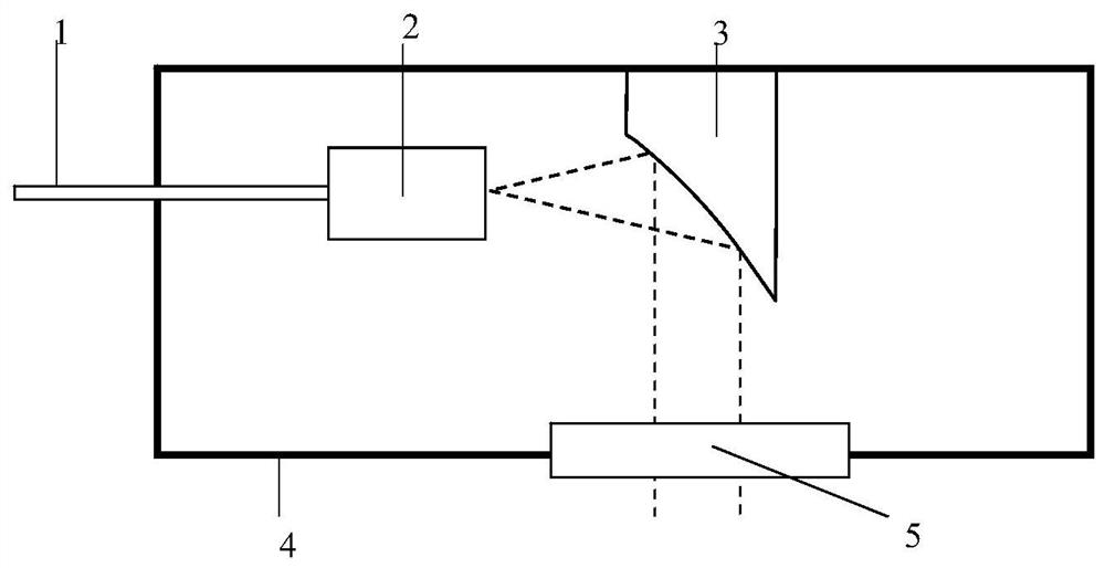
[0045] Such as figure 1 A schematic of the fiber collimator is shown. figure 1 The fiber collimator shown includes a broadband optical fiber 1, an optical fiber end cap 2, an off-axis parabolic reflector 3 and a package module 4, and the broadband optical fiber 1, the fiber end cap 2 and the off-axis parabolic reflector 3 are installed inside the package module 4 , the output port of the fiber end cap 2 is located at the focal point of the off-axis parabolic mirror 3 , and the package module 4 is provided with a window mirror 5 , and the window mirror 5 is located on the output optical path of the off-axis parabolic mirror 3 .
[0046] In this embodiment, the broadband optical fiber 1 adopts a photonic crystal fiber with a core diameter of 3 μm, a duty cycle of 0.4, a cladding diameter of 125 μm, and a coating diameter of 250 μm. The fusion splicer is discharged at half the standard intensity until completely collapsed. Cut under a microscope so that the length of the collap...
Embodiment 2
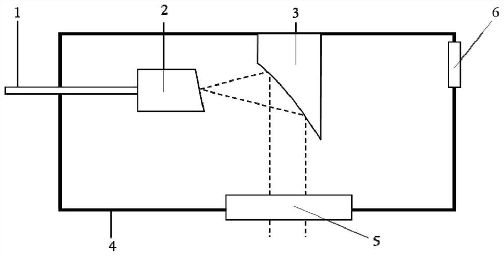
[0048] Such as figure 2 Shown is a schematic diagram of a fiber collimator with gas path inlet and outlet. figure 2 The fiber collimator shown includes a broadband optical fiber 1, an optical fiber end cap 2, an off-axis parabolic reflector 3 and a package module 4, and the broadband optical fiber 1, the fiber end cap 2 and the off-axis parabolic reflector 3 are installed inside the package module 4 , the output port of the fiber end cap 2 is located at the focal position of the off-axis parabolic reflector 3, the package module 4 is provided with a window mirror 5, and the window mirror 5 is located on the output optical path of the off-axis parabola reflector 3, the package module There is also a gas path inlet and outlet interface 6, the gas path inlet and outlet interface 6 has two channels of inlet and outlet, when transmitting a beam of a specific spectral range, a specific gas cycle can be selected to fill the cavity of the packaging module 4, reducing the absorption lo...
Embodiment 3
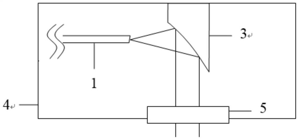
[0051] Such as image 3 A schematic of a fiber collimator without fiber end caps is shown. image 3 The shown fiber collimator comprises a broadband optical fiber 1, an off-axis parabolic mirror 3 and a packaging module 4, the broadband optical fiber 1 and the off-axis parabolic mirror 3 are installed inside the packaging module 4, and the output port of the broadband optical fiber is located off-axis The focus position of the off-axis parabolic reflector 3 , the package module 4 is provided with a window mirror 5 , and the window mirror 5 is located on the output optical path of the off-axis parabolic reflector 3 .
[0052] In this embodiment, the broadband optical fiber 1 is a quartz optical fiber with a core diameter of 25 μm and a cladding diameter of 250 μm. The coating layer with a length of 7 cm is stripped from the tail end, and the end face of the optical fiber is cut with an 8-degree bevel angle using a fiber cutter. . The near-infrared supercontinuum is obtained i...
PUM
| Property | Measurement | Unit |
|---|---|---|
| diameter | aaaaa | aaaaa |
| diameter | aaaaa | aaaaa |
Abstract
Description
Claims
Application Information
 - R&D
- Intellectual Property
- Life Sciences
- Materials
- Tech Scout
- Unparalleled Data Quality
- Higher Quality Content
- 60% Fewer Hallucinations
Browse by: Latest US Patents, China's latest patents, Technical Efficacy Thesaurus, Application Domain, Technology Topic, Popular Technical Reports.
© 2025 PatSnap. All rights reserved.Legal|Privacy policy|Modern Slavery Act Transparency Statement|Sitemap|About US| Contact US: help@patsnap.com


