
Display substrate, preparation method thereof and display device

A technology for display substrates and substrates, which is used in semiconductor/solid-state device manufacturing, electrical components, diodes, etc., and can solve problems such as pinhole color shift

Pending Publication Date: 2021-01-22
BOE TECH GRP CO LTD
View PDF4 Cites 7 Cited by
  • Summary
  • Abstract
  • Description
  • Claims
  • Application Information

AI Technical Summary

Problems solved by technology

However, during the display process of the display device, there will be color shift around the small hole

Method used


Image

  • Display substrate, preparation method thereof and display device
  • Display substrate, preparation method thereof and display device
  • Display substrate, preparation method thereof and display device

Examples


Embodiment Construction

[0056] In order to make the purpose, technical solution and advantages of the present disclosure clearer, the embodiments of the present disclosure will be described in detail below in conjunction with the accompanying drawings. It should be noted that, in the case of no conflict, the embodiments in the present disclosure and the features in the embodiments can be combined arbitrarily with each other.

[0057] The display panel based on COE technology uses a color filter structure layer composed of a black matrix and a color filter unit to replace the polarizer. Since the thickness of the general polarizer is about 50 microns, and the thickness of the color filter structure layer is generally about 10 microns, so , Compared with conventional polarizer display panels, display panels based on COE technology are thinner and easier to bend or curl.

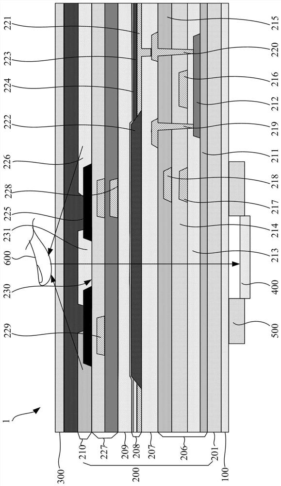
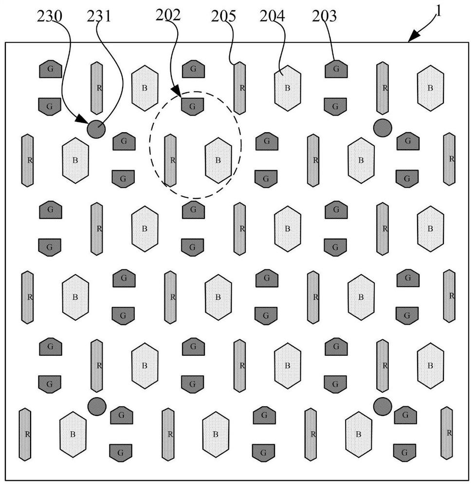
[0058] figure 1 is a structural schematic diagram of a display panel, figure 2 for figure 1 A plan view of the display panel sho...


PUM

PropertyMeasurementUnit
thicknessaaaaaaaaaa

Abstract

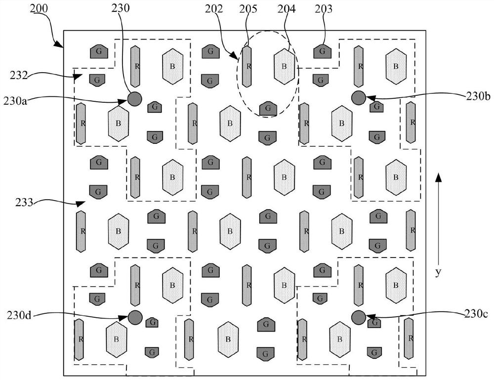
The invention discloses a display substrate, a preparation method thereof and a display device. The display substrate comprises a plurality of pixel units, and each pixel unit comprises a plurality ofsub-pixels, wherein each sub-pixel comprises a first color sub-pixel, each sub-pixel comprises a color film structure layer, and each color film structure layer comprises a black matrix for limitinga pixel opening and a color film unit for covering the pixel opening. The display substrate comprises a first display area and a second display area located on the periphery of the first display area,small holes are formed in a black matrix of the first display area, the small holes are filled with light filtering units, and the light filtering units are made of the same material as color film units of the first color sub-pixels. The area of the first color sub-pixel of the first display area is less than the area of the first color sub-pixel of the second display area. The color cast of thefirst display area is eliminated by setting the area of the first color sub-pixel of the first display area to be less than the area of the first color sub-pixel of the second display area.

Description

technical field [0001] The present disclosure relates to the field of display technology, and more specifically, to a display substrate, a manufacturing method thereof, and a display device. Background technique [0002] Organic Light Emitting Diode (OLED) is an active light-emitting display device, which has the advantages of self-illumination, wide viewing angle, high contrast, low power consumption, and extremely high response speed. With the continuous development of display technology, OLED technology is more and more applied to flexible display devices. [0003] In order to make the flexible display device thinner and easier to bend or fold, one solution is to use a color filter unit (Color Filter, CF) with a thickness of less than 10 microns in the display panel instead of a polarizer (Polarizer, POL), that is, to use a color-resisting structure (CF on Encapsulation, COE) technology. The optical fingerprint recognition of the display device based on COE technology n...

Claims


Application Information

Patent Timeline
Patent Type & Authority Applications(China)
IPC IPC(8): H01L27/32H01L21/77
CPCH10K59/352H10K59/60H10K59/353H10K59/38H10K59/40H10K59/12H10K59/1201H10K59/8792H10K59/65H10K50/865
Inventor 祝文秀杨华玲王博
Owner BOE TECH GRP CO LTD
Learn More