
Cable fixing clamp

A technology for fixing clips and cables, applied in the direction of electrical components, etc., can solve the problems of easy sliding, falling out, and single function of cables, and achieve the effects of improving use efficiency, avoiding displacement, and good flexibility

Pending Publication Date: 2021-01-22
CHANGZHOU ZHONGKE XINGLONG WIRE & CABLE
View PDF0 Cites 0 Cited by
  • Summary
  • Abstract
  • Description
  • Claims
  • Application Information

AI Technical Summary

Problems solved by technology

[0003] The existing cable fixing clips for power cable laying are fixed in structure and have a single function. They are generally composed of a sliding seat embedded in the track base, an adjustable upper pad inside the sliding seat, and a lower pad horizontally placed on the track. The lower pad lacks matching fixing devices, and it is easy to come off from the track, and the upper and lower pads cannot clamp the cable stably, and the side of the cable is easy to slide, which affects the normal use of the cable to a certain extent

Method used


Image

  • Cable fixing clamp
  • Cable fixing clamp

Examples


Embodiment Construction

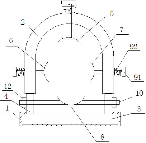
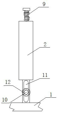
[0015]Such asfigure 1 It is a schematic structural diagram of the present invention. A cable fixing clip includes a slide rail base 1 and a cable rack 2. The cable rack 2 is slidably connected to the slide rail base 1 through a slider 3 at the bottom, and the slider 3 and the cable rack 2 pass through it. The connecting plates 4 at both ends are fixedly connected. The inner side of the cable rack 2 is provided with an upper block 5, a left block 6, a right block 7 and a lower block 8, which are used to clamp the cables to be fixed. The upper block 5 and the left block 6 and the right cushion block 7 are both movably connected with the cable rack 2 through an elastic screw adjusting mechanism 9. Two ends of the lower cushion block 8 are provided with adjusting rods 10, and the elastic screw adjusting mechanism 9 is composed of a T-shaped screw 91 and a spring 92. 91 penetrates through the cable rack 2, a spring 92 is arranged between the T-shaped screw 91 and the outer surface of the...


PUM


Abstract

The invention relates to the technical field of cable equipment, in particular to a cable fixing clamp which comprises a sliding rail base and a cable frame, the cable frame is slidably connected withthe sliding rail base through a sliding block at the bottom of the cable frame, and the sliding block and the cable frame are fixedly connected through connecting plates at the two ends. An upper cushion block, a left cushion block, a right cushion block and a lower cushion block which are used for clamping a cable to be fixed are arranged on the inner side face of the cable frame, the upper cushion block, the left cushion block and the right cushion block are movably connected with the cable frame through elastic screw adjusting mechanisms, adjusting rods are arranged at the two ends of thelower cushion block, and adjusting grooves matched with the adjusting rods are formed in the connecting plates. The adjusting groove is perpendicular to the sliding rail base, the elastic screw adjusting mechanism is composed of a T-shaped screw and a spring, the T-shaped screw penetrates through the cable frame, the cable in the cable frame is stably clamped through cushion blocks in four directions, displacement of the cable is avoided, the cushion blocks can be driven by the screw to be adjusted, limited and fixed, flexibility is good, and universality is high. The use efficiency of the fixing clamp is effectively improved.

Description

Technical field[0001]The invention relates to the technical field of cable equipment, in particular to a cable fixing clip.Background technique[0002]The cable clamp is also known as the cable fixing frame. Because of the high altitude operation, the particularity is self-evident. It can be said that the use and operation of the cable are very dangerous, and it needs secondary protection. The creation and application of the cable clamp is easy Solving the above problems, it has unique charm and safety, but its small body contains positive energy for protection. It has to be said that this has played a big role in the operation of the cable.[0003]The existing cable fixing clip for power cable laying has a fixed structure and a single function. It is generally composed of a sliding seat embedded in the rail seat, an adjustable upper block inside the sliding seat, and a lower block horizontally arranged on the track. The lower block lacks supporting fixing devices and is easy to come of...

Claims


Application Information

Patent Timeline
Patent Type & Authority Applications(China)
IPC IPC(8): H02G3/32
CPCH02G3/32
Inventor 汤明芳
Owner CHANGZHOU ZHONGKE XINGLONG WIRE & CABLE
Learn More