Over-voltage protection arrangement having a horn gap located in an insulating housing having a deionization chamber for arc extinguishing

A technology for protection devices and spark gaps, which can be used in overvoltage arresters with spark gaps, emergency protection devices, spark gaps with auxiliary trigger devices, etc., and can solve problems such as destroying fuses

Active Publication Date: 2021-01-22
デーンエスエープルスツェオーカーゲー
View PDF7 Cites 0 Cited by
  • Summary
  • Abstract
  • Description
  • Claims
  • Application Information

AI Technical Summary

Problems solved by technology

This destroys the fuse

Method used


Image

  • Over-voltage protection arrangement having a horn gap located in an insulating housing having a deionization chamber for arc extinguishing
  • Over-voltage protection arrangement having a horn gap located in an insulating housing having a deionization chamber for arc extinguishing
  • Over-voltage protection arrangement having a horn gap located in an insulating housing having a deionization chamber for arc extinguishing

Examples


Embodiment Construction

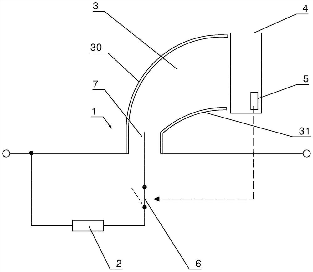
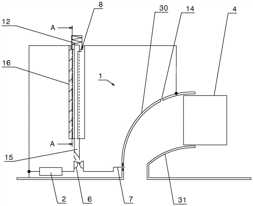
[0047] according to figure 1 The overvoltage protection device is based on a spark gap 1 with a trigger circuit 2. The spark gap has two stylized arc-shaped corner electrodes 30 , 31 which form the arc-running region 3 . Ignition or auxiliary electrodes 7 are located in the foot region of corner electrodes 30 , 31 and are connected to trigger circuit 2 .

[0048] The disconnecting element 6 , which is configured, for example, as a switch, can interrupt the connection between the ignition electrode or the auxiliary electrode 7 and the triggering circuit 2 .

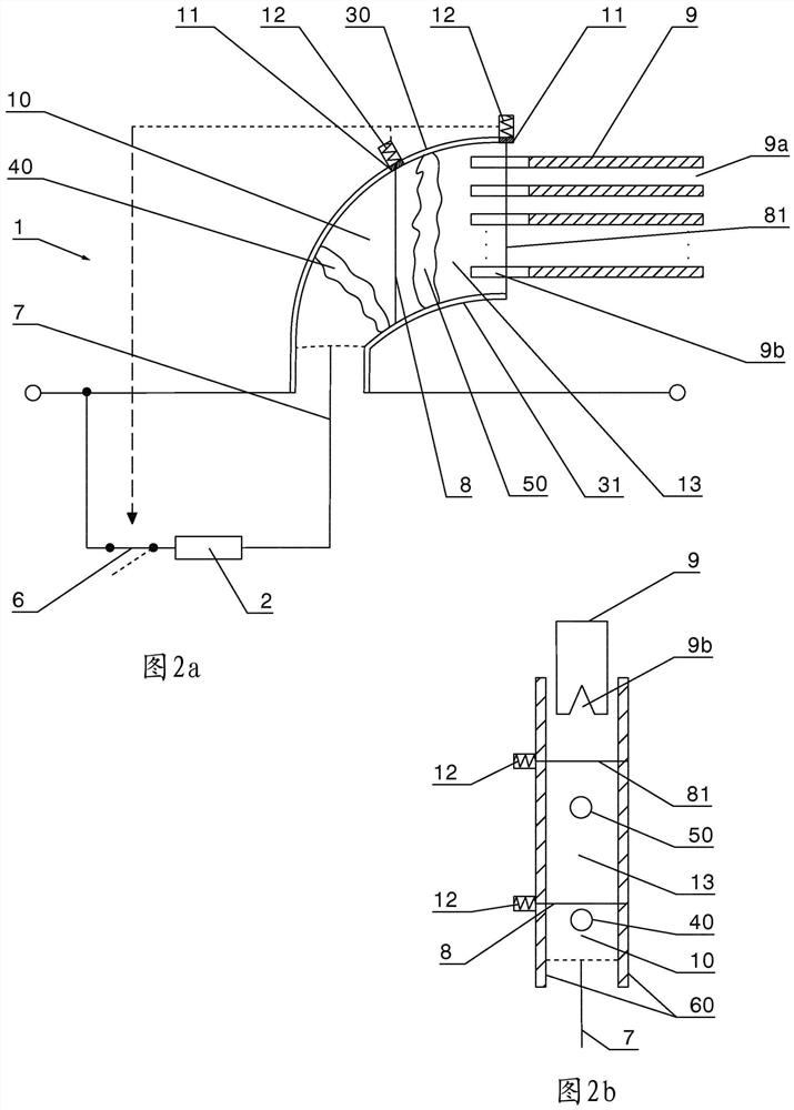
[0049] The arc travel area 3 is followed by a deionization or arc chute 4 which houses a plurality of deionization or arc chute plates (not shown).

[0050] The evaluation unit 5 is located in the region of the deion chamber 4 .

[0051] The evaluation unit 5 is formed by a fuse in the form of a wire. When the fuse is overloaded, the disconnect element or switch 6 is activated (schematically indicated by an arrow) to i...


PUM


Abstract

The invention relates to an over-voltage protection arrangement comprising a horn gap (1) located in an insulating housing having a deionization chamber (4) for arc extinguishing, wherein the deionization chamber has a plurality of extinguishing plates (9), which are spaced apart from each other, and a trigger electrode (7) is located in the ignition region of the horn gap, wherein a disconnectingdevice has a fuse element (8), which is located in the region of the deionization chamber, and is subjected to a load there caused by power follow current, wherein the fuse element holds a, preferably spring force supported, disconnecting element (15) in a first position and releases said disconnecting element upon melting, such that the disconnecting element assumes a second position, wherein, upon the second position being reached, an electrical connection to the trigger electrode (7) is interrupted and the trigger electrode is thus disconnected.

Description

technical field [0001] The invention relates to an overvoltage protection device according to the preamble of claim 1 , comprising a corner spark gap in an insulating housing, the corner spark gap having a deionization chamber for arc extinguishing, said deionization chamber having A plurality of spaced apart arc chute and trigger electrodes are located in the ignition region of the corner spark gap. Background technique [0002] An angular spark gap with a deion chamber for arc extinguishing is known, for example, from DE 10 2011 051 738 A1. The associated angular spark gap is located in the housing and has means for controlling the internal gas flow in order to adjust the different characteristics of the arc caused by the pulsed current load on the one hand and the arc caused by the grid freewheeling on the other hand. [0003] In a known corner spark gap, the trigger electrode can be arranged in the ignition region. The trigger electrode may comprise a conductive elemen...

Claims


Application Information

Patent Timeline
IPC IPC(8): H01T1/14H01T2/02H01T4/14
CPCH01T4/14H01H85/44H01T1/14H01H9/46H01H9/32H01T2/02H01T1/02H01H85/0241H01H85/055H01H85/165
Inventor A·埃尔哈特H·希尔施曼S·哈斯G·维特曼
Owner デーンエスエープルスツェオーカーゲー
Why Eureka
Try Eureka