
Efficient vaccine inactivation device

A high-efficiency and inactivation technology, applied in water supply equipment, sanitary equipment for toilets, heating, etc., can solve the problems of inactivated vaccine pollution, time required, temperature control deviation, etc., to improve success efficiency, accurate temperature, The effect of increasing the success rate

Active Publication Date: 2021-01-26
AB&B BIO TECH CO LTD JS
View PDF7 Cites 0 Cited by
  • Summary
  • Abstract
  • Description
  • Claims
  • Application Information

AI Technical Summary

Problems solved by technology

[0003] Most of the traditional vaccine inactivation methods use physical inactivation. Traditional physical inactivation uses a single method of heating to kill viruses or a single method of ultrasonic cracking cells. The inactivation effect is not ideal and the inactivation efficiency is not high; The success rate is low, and it is difficult to guarantee the purity of vaccines that are often needed; the jacket of the vaccine inactivation tank provides the required temperature by controlling the water temperature. The preparation work is long, which affects the overall inactivation efficiency; most of the existing inactivation devices are non-airtight devices, which will cause the original inactivated vaccine to be polluted in a non-airtight environment, which will affect the inactivation efficiency; The automation level of the living device is not high, and most of them are manually operated. Manual contact will pollute the inactivated vaccine, and the inactivation efficiency is low

Method used


Image

  • Efficient vaccine inactivation device
  • Efficient vaccine inactivation device

Examples


Embodiment Construction

[0013] The accompanying drawings are for illustrative purposes only, and should not be construed as limitations on this patent; in order to better illustrate this embodiment, certain components in the accompanying drawings will be omitted, enlarged or reduced, and do not represent the size of the actual product; for those skilled in the art It is understandable that some well-known structures and descriptions thereof may be omitted in the drawings.

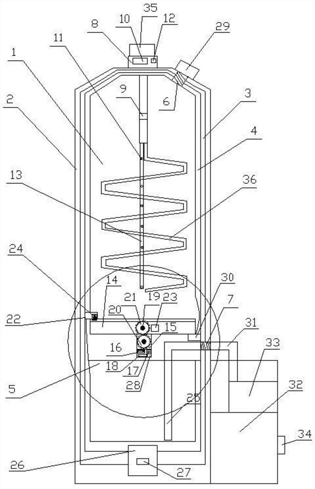
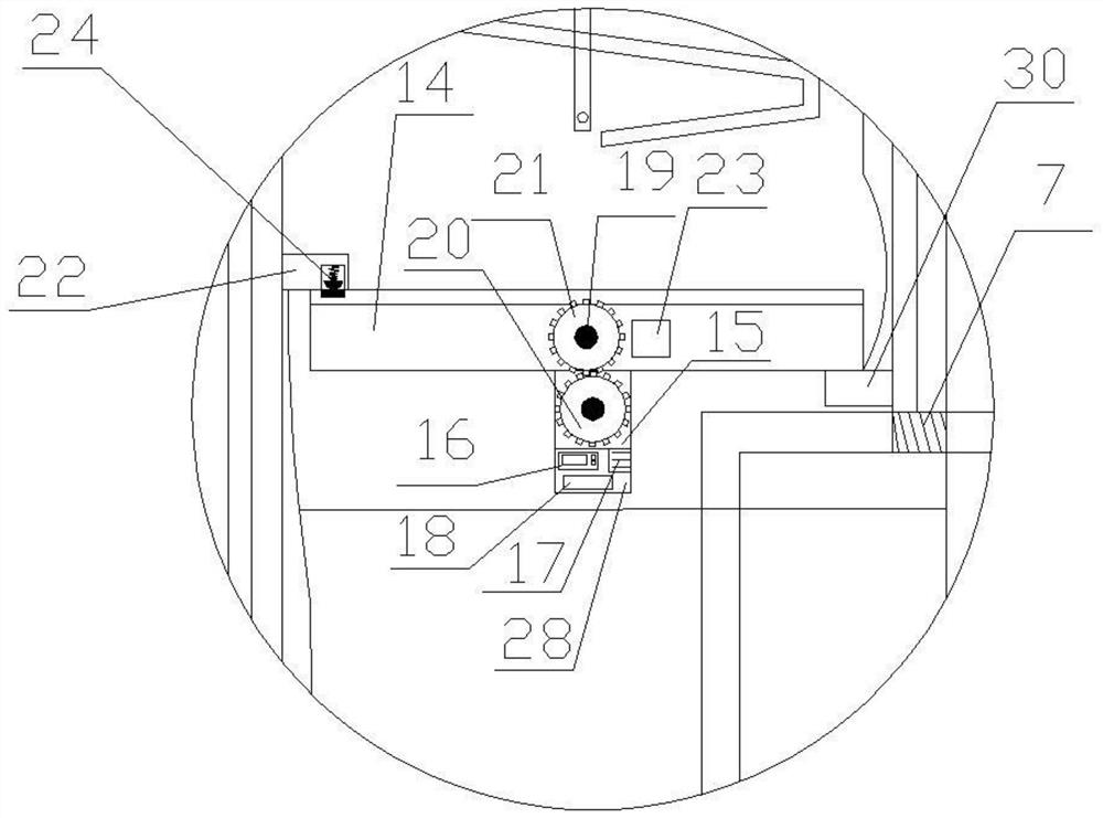
[0014] Referring to the accompanying drawings: a high-efficiency inactivation device for vaccines, comprising a tank, a feed port 6, a temperature sensing device 8, a stirring device, a discharge port 7 and an electric discharge device, the top of the tank is provided with a feed Port 6 and temperature sensing device 8, a stirring device is arranged below the temperature sensing device 8, and the stirring device is arranged inside the tank body, the timing switch valve is arranged inside the tank body, and the The bottom of the ta...


PUM


Abstract

Disclosed is an efficient vaccine inactivation device. The efficient vaccine inactivation device comprises a tank body, a feeding port, a temperature sensing device, a stirring device, a discharging port and an electric discharging device; the feeding port and the temperature sensing device are arranged at the top end of the tank body; the stirring device is arranged below the temperature sensingdevice; the stirring device is arranged in the tank body; a timing switch is arranged inside the tank body; an ultrasonic generator is arranged at the bottom of the tank body; the discharging port isformed in the tank wall of the tank body; the discharging port is connected with the electric discharging device; and the electric discharging device is arranged on one side of the tank body. In the aspect of temperature control, an electric heating layer is adopted for direct heating, so that the temperature is accurate, clear and easy to control; an internal temperature sensing probe is adopted,so that the temperature needed by inactivation is directly monitored, deviation is reduced, and the inactivation success rate is greatly increased; and the ultrasonic generator is additionally arranged, so that the ultrasonic generator further achieves the inactivation effect.

Description

technical field [0001] The invention relates to the technical field of pharmaceutical production, in particular to a high-efficiency inactivation device for vaccines. Background technique [0002] Inactivated vaccines refer to culturing viruses or bacteria first, and then inactivating them with heating, chemical reagents and ultrasonic waves. Inactivated vaccines can be composed of whole viruses or bacteria. [0003] Most of the traditional vaccine inactivation methods use physical inactivation. Traditional physical inactivation uses a single method of heating to kill viruses or a single method of ultrasonic cracking cells. The inactivation effect is not ideal and the inactivation efficiency is not high; The success rate is low, and it is difficult to guarantee the purity of vaccines that are often needed; the jacket of the vaccine inactivation tank provides the required temperature by controlling the water temperature, and the temperature control often has deviations, and t...

Claims


Application Information

Patent Timeline
IPC IPC(8): A61L2/04A61L2/025A61L2/26A61L2/24
CPCA61L2/0011A61L2/0023A61L2/24A61L2/26A61L2202/14A61L2202/21
Inventor 陈晓芬冷文娜刘金鑫葛灵睿姜洪艳秦奇
Owner AB&B BIO TECH CO LTD JS
Learn More