
Rack oiling device

A technology for applying oil to a rack and an oil pump, applied in the field of machinery, can solve problems such as being easy to be blocked, and achieve the effect of avoiding easy blocking.

Pending Publication Date: 2021-01-26
湖南台锯科技有限公司
View PDF0 Cites 0 Cited by
  • Summary
  • Abstract
  • Description
  • Claims
  • Application Information

AI Technical Summary

Problems solved by technology

[0002] The surface of the rack needs to be oiled during production. The existing oiling device usually uses an atomizing nozzle for spraying, but the atomizing nozzle is a small-aperture nozzle, which makes it easy to be blocked

Method used


Image

  • Rack oiling device

Examples


Embodiment 1

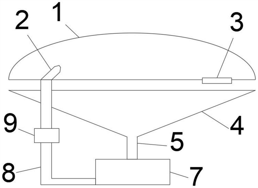
[0014] Such as figure 1 A rack oiling device shown includes an elliptical cover plate 1, a high-pressure spray nozzle 2 is installed at one focus of the elliptical cover plate 1, and the other focus forms a passage through which the rack 3 passes; the elliptical cover plate A recovery hopper 4 is installed below 1, the bottom of the recovery hopper 4 is a discharge port 5, and the bottom of the discharge port 5 is an oil storage tank 7, which communicates with the high-pressure nozzle 2 through a communication pipe 8; an oil pump 9 is installed on the communication pipe 8.

[0015] The oil pump 9 is a high-pressure oil pump. The connecting pipe 8 communicates with the bottom of the fuel tank 7 .

[0016] The oval cover plate 1 is a stainless steel plate. Recovery hopper 4 is conical.

[0017] The invention utilizes the principle that the light emitted from one focal point of the ellipse must pass through the other focal point after reflection, and the oil sprayed by the hig...


PUM


Abstract

The invention discloses a rack oiling device which comprises an oval cover plate, wherein a high-pressure spray head is mounted at one focus of the oval cover plate, and a channel allowing a rack to pass through is formed in the other focus of the oval cover plate; a recycling hopper is mounted below the oval cover plate, a discharge hole is formed in the bottom of the recycling hopper, and an oilstorage tank is arranged at the bottom of the discharge hole and communicates with a high-pressure spray head through a communication tube; and an oil pump is mounted on the communication tube. By means of the principle that light emitted from one focus of the ellipse is reflected to inevitably pass through the other focus, oil sprayed by a high-pressure spray head is atomized after being collided by the oval cover plate, then falls on the other focus and falls on the surface of the rack to achieve rapid oiling, so that the defect that in the prior art, a spray head is prone to being blockedis overcome.

Description

technical field [0001] The invention belongs to the field of machinery, in particular to a rack oiling device. Background technique [0002] The rack needs to be oiled on the surface during manufacture, and the existing oiling device usually uses an atomizing nozzle for spraying, but the atomizing nozzle is a nozzle with a small aperture, which makes it easy to be blocked. Contents of the invention [0003] In order to solve the above problems, the present invention provides a rack oiling device. The invention utilizes the principle that the light emitted from one focal point of the ellipse must pass through the other focal point after reflection, and the oil sprayed by the high-pressure nozzle is atomized after colliding with the elliptical cover plate, and then falls on the other focal point and falls on the surface of the rack to realize rapid It is oiled, and avoids the defect that the nozzle of the prior art is easy to be blocked. [0004] For reaching above-mention...

Claims


Application Information

Patent Timeline
Patent Type & Authority Applications(China)
IPC IPC(8): B05B13/00B05B14/00
CPCB05B13/00B05B14/00Y02P70/10
Inventor 卢达巷
Owner 湖南台锯科技有限公司
Learn More