Spine wave recognition method and device, electronic equipment and storage medium

An identification method and computer technology, applied in the medical field, can solve the problems of single-angle features and low accuracy of spike wave identification, and achieve the effect of improving detection accuracy

Active Publication Date: 2021-01-26
苏州国科康成医疗科技有限公司
View PDF6 Cites 0 Cited by
  • Summary
  • Abstract
  • Description
  • Claims
  • Application Information

AI Technical Summary

Problems solved by technology

However, the inventors found that the existing spike recognition analysis is limited to a single viewing angle feature, resulting in a low accuracy rate of spike recognition using this method

Method used


Image

  • Spine wave recognition method and device, electronic equipment and storage medium
  • Spine wave recognition method and device, electronic equipment and storage medium
  • Spine wave recognition method and device, electronic equipment and storage medium

Examples


Embodiment 1

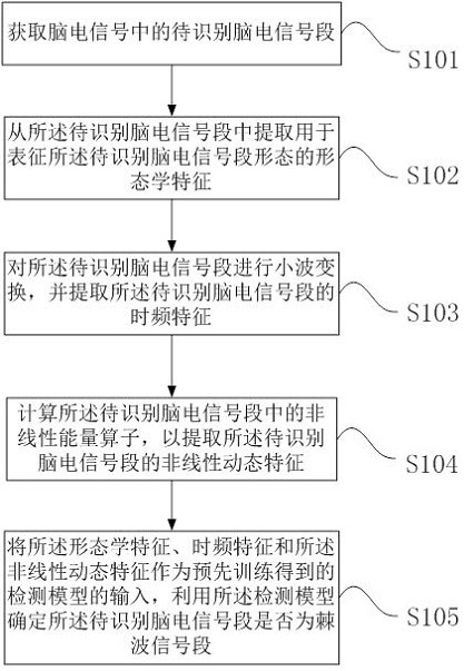
[0071] This embodiment provides a spike recognition method, figure 1 It is to illustrate that according to some embodiments of the present invention, by extracting the morphological features, time-frequency features and nonlinear dynamic features of the EEG signal segment to be identified, and using the extracted multi-view features as the input of the detection model, to identify A flow chart of whether the EEG signal segment to be identified is a spike wave signal segment. Although the processes described below include operations in a particular order, it should be clearly understood that these processes may also include more or fewer operations, which may be performed sequentially or in parallel (e.g., using parallel processors or multi-threaded environment).

[0072] This embodiment provides a spike identification method, which is used to identify the category of the EEG signal segment to be identified, such as figure 1 shown, including the following steps:

[0073] S10...

Embodiment 2

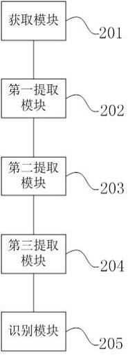
[0129] This embodiment provides a spike identification device for identifying and judging spike signal segments and non-spike signal segments in EEG signals, such as figure 2 shown, including:

[0130] The acquisition module 201 is configured to acquire the EEG signal segment to be identified in the EEG signal; for details, please refer to the relevant description of step S101 in Embodiment 1, and details will not be repeated here.

[0131] The first extraction module 202 is configured to extract, from the EEG signal segment to be identified, morphological features for characterizing the shape of the EEG signal segment to be identified; for details, please refer to the relevant description of step S102 in Embodiment 1, I won't repeat them here.

[0132] The second extraction module 203 is configured to perform wavelet transform on the EEG signal segment to be identified, and extract the time-frequency features of the EEG signal segment to be identified; for details, please r...

Embodiment 3

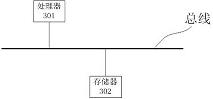
[0137] This embodiment provides an electronic device, such as image 3 As shown, the device includes a processor 301 and a memory 302, wherein the processor 301 and the memory 302 can be connected through a bus or in other ways, image 3 Take connection via bus as an example.

[0138] The processor 301 may be a central processing unit (Central Processing Unit, CPU). The processor 301 can also be other general-purpose processors, digital signal processors (Digital Signal Processor, DSP), graphics processors (Graphics Processing Unit, GPU), embedded neural network processors (Neural-network Processing Unit, NPU) or other Dedicated deep learning coprocessor, Application Specific Integrated Circuit (ASIC), Field-Programmable Gate Array (FPGA) or other programmable logic devices, discrete gate or transistor logic devices, discrete hardware components and other chips, or a combination of the above-mentioned types of chips.

[0139] The memory 302, as a non-transitory computer-rea...


PUM


Abstract

The invention relates to a spine wave recognition method and device, electronic equipment and a storage medium. The spine wave recognition method comprises the steps that a to-be-recognized electroencephalogram signal segment in an electroencephalogram signal is acquired; morphological characteristics used for representing the morphology of the to-be-recognized electroencephalogram signal segmentare extracted from the to-be-recognized electroencephalogram signal segment; wavelet transformation is carried out on the to-be-recognized electroencephalogram signal segment, and time-frequency features of the to-be-recognized electroencephalogram signal segment are extracted; a nonlinear energy operator in the to-be-recognized electroencephalogram signal segment is calculated to extract nonlinear dynamic characteristics of the to-be-recognized electroencephalogram signal segment; and the morphological characteristics, the time-frequency characteristics and the nonlinear dynamic characteristics are taken as input of a detection model obtained by pre-training, and it is determined whether the to-be-recognized electroencephalogram signal segment is a ratchet signal segment or not by utilizing the detection model. Compared with the mode of recognizing the to-be-recognized electroencephalogram signal segment only from a single angle, the method has the advantages that the to-be-recognizedelectroencephalogram signal segment is recognized from three angles, the considered related information is more comprehensive, and therefore the final detection accuracy can be improved.

Description

technical field [0001] The present invention relates to the medical field, in particular to a spike recognition method, device, electronic equipment and computer-readable storage medium. Background technique [0002] Epilepsy is a neuromuscular disorder, and scalp EEG-based epilepsy treatments are widely used in clinical practice because of their accessibility, non-invasiveness, and cost-effectiveness. Epilepsy analysis includes the detection of abnormal EEG patterns and EEG signals for the diagnosis and management of epilepsy. The origin of abnormal EEG signals in electroencephalogram (EEG) has a good consistency with the epileptogenic zone, so locating abnormal EEG signals can be used for evaluation before and after surgery in patients with intractable epilepsy. [0003] Most of the existing spike detection technologies are based on intracranial EEG signals, which need to be recorded by implanting electrodes into the patient's craniotomy, causing a great physical and psyc...

Claims


Application Information

Patent Timeline
Patent Type & Authority Applications(China)
IPC IPC(8): G06K9/00
CPCG06V40/15G06F2218/06G06F2218/08G06F2218/12
Inventor 戴亚康刘燕胡保华彭博
Owner 苏州国科康成医疗科技有限公司
Why Eureka
Try Eureka