Universal wire connecting device and connecting method thereof
A connecting device and wire technology, applied in the direction of conductive connection, connection, electrical component connection, etc., can solve problems affecting the use, potential safety hazards of wires, wire locking interference, etc., to achieve firm and reliable clamping, improve use safety, and ensure unrevealed effect
- Summary
- Abstract
- Description
- Claims
- Application Information
AI Technical Summary
Problems solved by technology
Method used
Image

Examples
Embodiment Construction
[0038] The present invention will be described in further detail below in conjunction with the accompanying drawings, but it is not intended to limit the protection scope of the present invention.
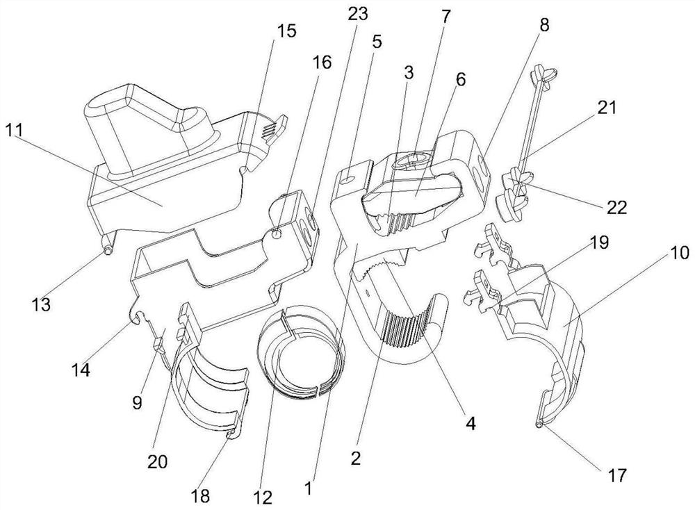
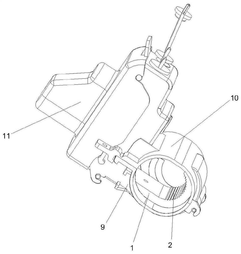
[0039] Such as Figure 1-4 As shown, a wire universal connection device includes a connector body 1, a main line clamping part installed on the connector main body 1, a branch line clamping part and an insulating shell;
[0040] The connector main body 1 is provided with a main line clamping position 2 matching the main line clamping part and a branch line clamping position 3 matching the branch line clamping part;
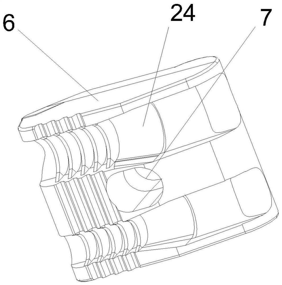
[0041] The clamping part of the main line includes the main line pressing block 4 matching the main line clamping position 2 and the main line fastening bolt matching the main line pressing block 4, and the connector main body 1 is provided with the first bolt matching the main line fastening bolt hole 5;
[0042] The branch line clamping part includes a branch line ...
PUM
| Property | Measurement | Unit |
|---|---|---|
| Length | aaaaa | aaaaa |
| Length | aaaaa | aaaaa |
Abstract
Description
Claims
Application Information