
Switching element unit and switching element module

A technology of switching elements and switching element groups, which is applied in the direction of electrical components, semiconductor/solid-state device parts, electric solid-state devices, etc., and can solve the problems of open connection structure without electricity

Pending Publication Date: 2021-01-26
AISIN CORP
View PDF1 Cites 0 Cited by
  • Summary
  • Abstract
  • Description
  • Claims
  • Application Information

AI Technical Summary

Problems solved by technology

However, in Patent Document 1, there is no specific disclosure about such an electrical connection structure

Method used


Image

  • Switching element unit and switching element module
  • Switching element unit and switching element module
  • Switching element unit and switching element module

Examples


Embodiment Construction

[0019] Embodiments of a switching element unit and a switching element module will be described with reference to the drawings. In addition, terms related to dimensions, arrangement directions, arrangement positions, etc. of each component in the following description are concepts that include states that have differences due to errors (errors of an acceptable level in manufacturing). In addition, in this specification, a "rotating electric machine" is used as a concept including a motor (electric motor), a generator (generator), and any one of the motor and the generator functioning as both the motor and the generator as necessary.

[0020] The switching element unit 10 is used in an inverter circuit 100 for power conversion between DC power and AC power (refer to Figure 7 ). Such as Figure 7 As shown, the inverter circuit 100 is provided between the DC power supply 6 (supply source of DC voltage) and the rotary electric machine MG. The DC power supply 6 is configured us...


PUM


Abstract

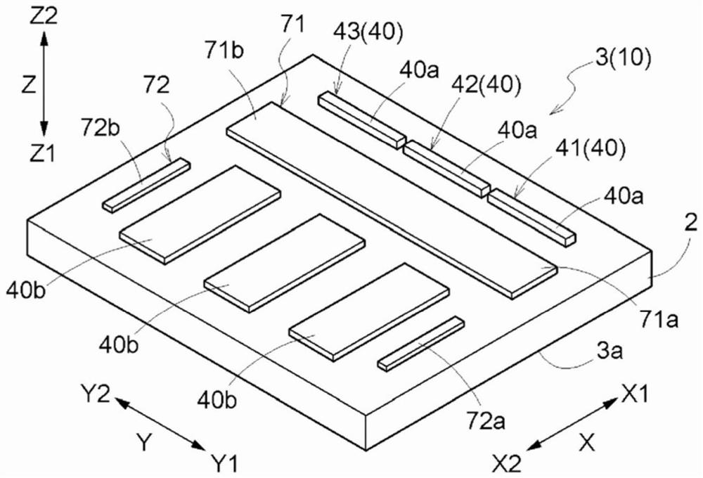
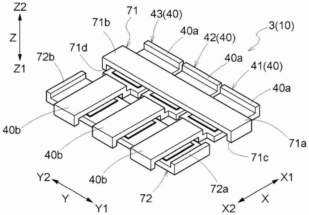
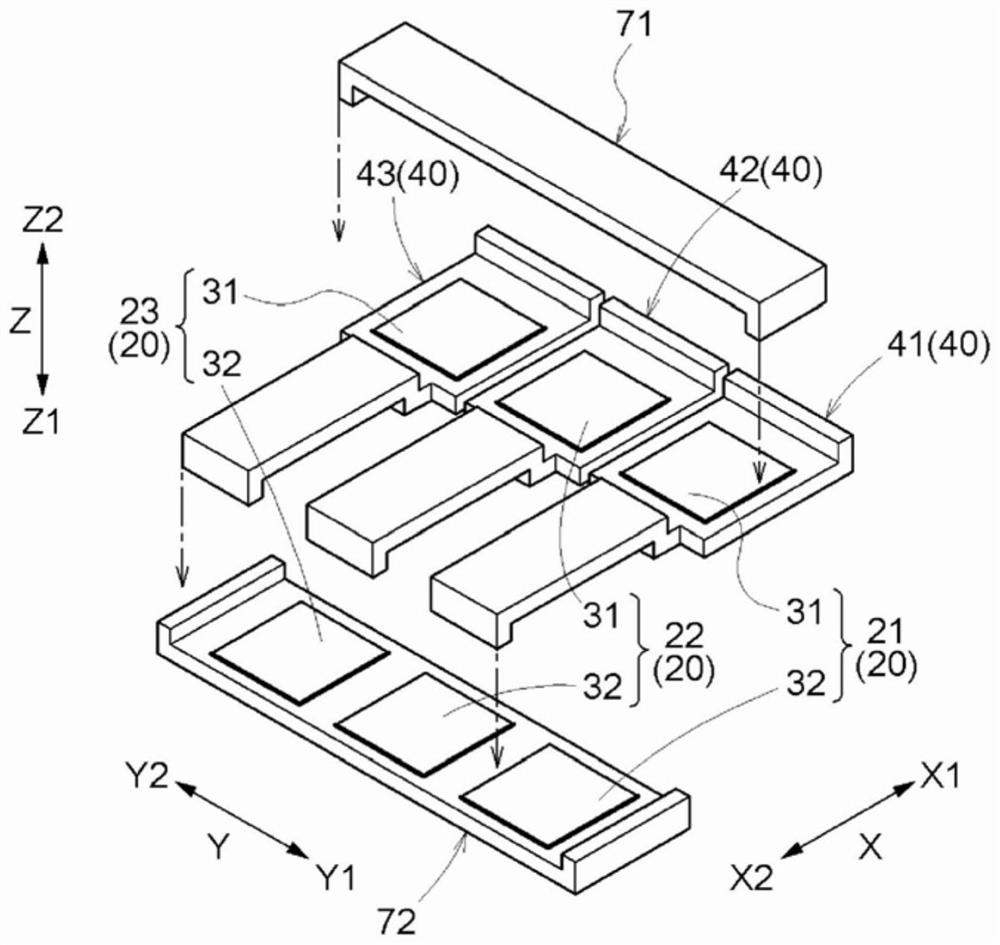
The present invention relates to a switching element unit and a switching element module. In the present invention, a first switching element (31) and a second switching element (32) are disposed so as to be arrayed in a first direction (X). An output busbar (40) is disposed along the first direction (X). The first switching element (31) and the second switching element (32) are disposed so as tobe embedded in a molded part (2). The output busbar (40) comprises: an embedded section (40c) that is embedded in the molded part (2); a first exposed section (40a) that is exposed from the molded part (2) on one side in the first direction (X) in relation to a switching element group (20); and a second exposed section (40b) that is exposed from the molded part (2) on another side in the first direction (X) in relation to the switching element group (20).

Description

technical field [0001] The present invention relates to a switching element unit including a switching element group constituting an inverter circuit, and a switching element module including a plurality of such switching element units. Background technique [0002] An example of such a switching element unit is described in JP-A-2002-369496 (Patent Document 1). Patent Document 1 discloses a process for preventing errors caused by unbalanced switching of power elements when intelligent power modules (IPMs) constituting an inverter circuit are connected in parallel and used. Current detection, heat concentration technology. Although it is not clearly described in Patent Document 1, by connecting the IPMs in parallel in this manner, the current capacity of the inverter circuit as a whole can be increased to drive large-capacity AC equipment. [0003] However, in the case of a structure in which the current capacity of the entire switching element module including a plurality...

Claims


Application Information

Patent Timeline
IPC IPC(8): H01L25/07H01L23/36H01L25/18H02M7/48
CPCH01L25/18H01L23/36H02M7/003H02M1/008H01L23/492H01L25/072H01L25/16H01L23/367H02M7/5387
Inventor 堀田丰大须贺慎也粂康弘岛野薰福原俊之池山健
Owner AISIN CORP
Learn More