

Multifunctional shoe storing and taking device based on comb type transportation
A multi-functional, comb-like technology, used in storage devices, transportation and packaging, household cleaning devices, etc., to achieve the effect of increasing the scope, expanding the way of use, and simplifying the way of use
- Summary
- Abstract
- Description
- Claims
- Application Information
AI Technical Summary
Problems solved by technology
Method used
Image

Examples
Embodiment Construction
[0024] The present invention will be further described below in conjunction with the accompanying drawings and embodiments.
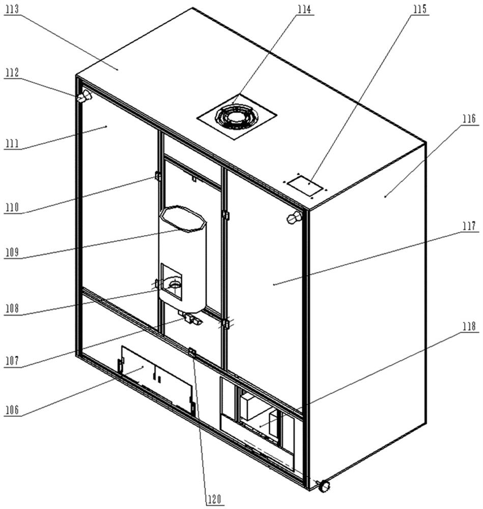
[0025] Such as figure 1 , figure 2 As shown, a multifunctional access shoe device based on comb-type transportation, including a cabinet body, a left shoe rack, a right shoe rack, an access shoe transmission device, a shoe access power device, a cleaning device, a wiper Shoe device 118, drying and disinfection device 114, control system, the cabinet body is a square box body mechanism composed of front vertical board, rear vertical board, left vertical board, right vertical board 116, top board 113 and bottom board, the front The upper left side of the vertical plate is provided with a left cabinet door 111 through the cabinet door hinge 110, and the left cabinet door 111 is provided with a cabinet door handle 112, and the left side shoe rack is provided at the position corresponding to the left cabinet door 111 in the cabinet, and the front vertical ...
PUM
 Abstract
Description
Claims
Application Information