
A Friction Welding Spindle Head Based on Support Rod Lateral Movement

A technology of lateral movement and spindle head, applied in the field of friction welding, can solve the problems of not being able to achieve a constant state, reducing the quality of friction welding, and vibration of the motor, and achieving the effects of reducing temperature, improving stability, and increasing load capacity

Active Publication Date: 2021-10-15
湖南坤鼎数控科技有限公司
View PDF8 Cites 0 Cited by
  • Summary
  • Abstract
  • Description
  • Claims
  • Application Information

AI Technical Summary

Problems solved by technology

[0003] But when the motor and the spindle head are installed in one piece, the motor will vibrate when it works, and then bring it to the spindle head to vibrate together, so the spindle head will shake, so that the torque generated by the rotation will change, and the applied pressure will not be constant. state, thereby reducing the quality of friction welding, resulting in a decline in the quality of products produced by the factory

Method used


Image

  • A Friction Welding Spindle Head Based on Support Rod Lateral Movement
  • A Friction Welding Spindle Head Based on Support Rod Lateral Movement
  • A Friction Welding Spindle Head Based on Support Rod Lateral Movement

Examples


Embodiment 1

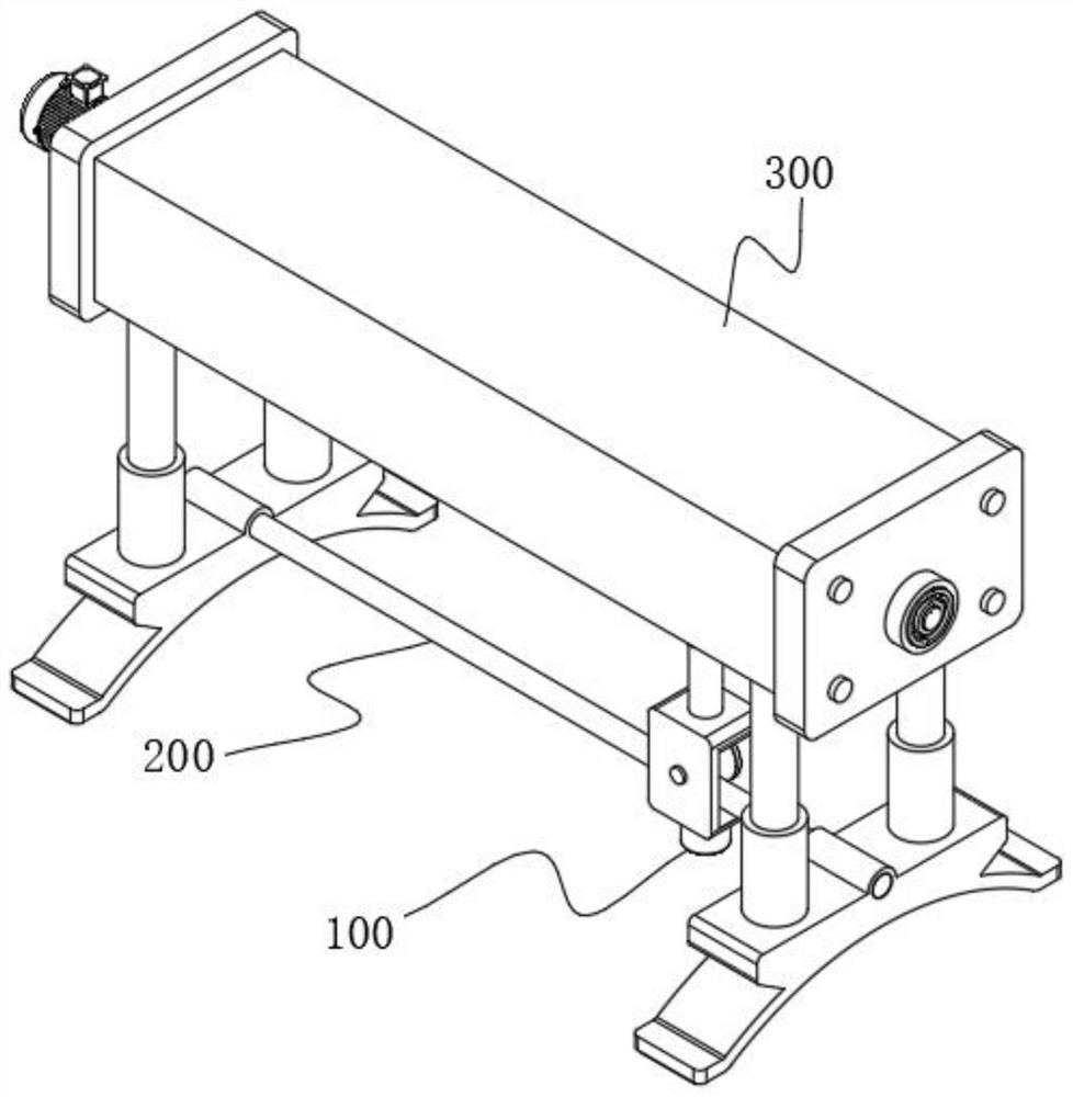
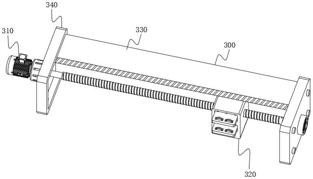
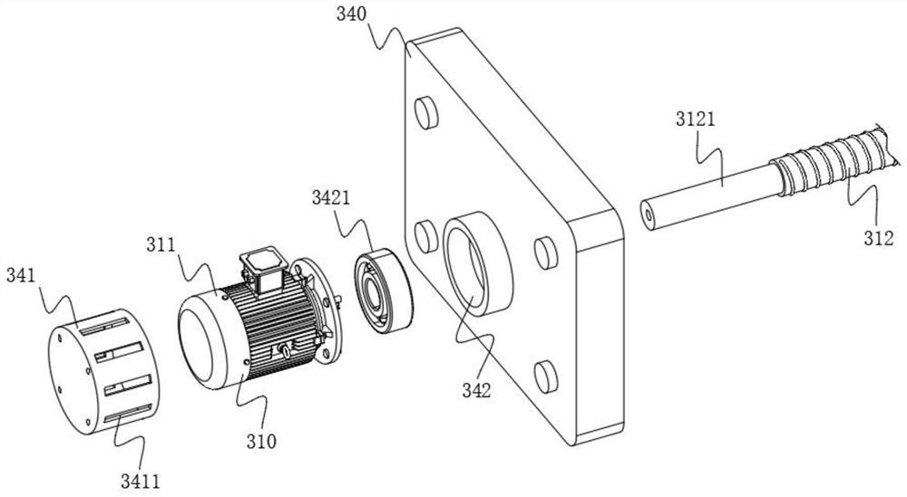
[0062] The present invention provides a friction welding spindle head based on support bar type lateral movement, please refer to Figure 1-Figure 10 , including a spindle head 100, a traverse mechanism 200 and a transmission mechanism 300 arranged on the top of the traverse mechanism 200, the traverse mechanism 200 includes a support rod 210, and support seats 220 are provided at both ends of the support rod 210, and the support seat 220 includes Support block 221, the middle position of the top of support block 221 is provided with insertion hole 2211, and support bar 210 is plugged with insertion hole 2211, thereby supports and fixes support bar 210 by support block 221, and the top of support block 221 is provided with Support rod 222, and support rod 222 is fixedly connected with transmission frame 330, and transmission frame 330 is supported by support rod 222, and transmission mechanism 300 comprises power unit 310 at least, and power unit 310 comprises motor 311, and th...


PUM


Abstract

The invention relates to the technical field of friction welding, in particular to a friction welding spindle head based on a support bar type lateral movement. It includes a spindle head, a traversing mechanism and a transmission mechanism arranged on the top of the traversing mechanism. The traversing mechanism includes a support rod, and both ends of the support rod are provided with support seats, and the support seats include support blocks. The middle position of the top of the support block is provided with an insertion hole, and the support rod is plugged and matched with the insertion hole. The top of the support block is provided with a support rod. The transmission mechanism includes a power device, and the power The device includes a motor, and a screw rod is arranged on the left side of the motor. In the present invention, the set motor drives the screw to rotate, and drives the transmission block and the traverse block to move, and the traverse block moves to drive the spindle head at the bottom to move, thereby realizing the separation of the spindle head and the motor, and then reducing the vibration of the motor to the spindle head. Impact.

Description

technical field [0001] The invention relates to the technical field of friction welding, in particular to a friction welding spindle head based on a support bar type lateral movement. Background technique [0002] Friction welding is under the action of pressure, under the action of constant or increasing pressure and torque, using the relative motion between the welding contact end faces to generate friction heat and plastic deformation heat on the friction surface and its surrounding areas, so that the surrounding areas The temperature rises to a temperature range close to but generally lower than the melting point. Generally, the rotation of the spindle head provides torque for the welding contact end surface, and then the motor drives the spindle head to move laterally. Usually, the motor and the spindle head in the factory are fixed on a support frame. superior. [0003] But when the motor and the spindle head are installed in one piece, the motor will vibrate when it ...

Claims


Application Information

Patent Timeline
Patent Type & Authority Patents(China)
IPC IPC(8): B23K20/12
CPCB23K20/1245
Inventor 罗益张新胜彭彪
Owner 湖南坤鼎数控科技有限公司
Learn More