
Circuit board soldering device for controller production

A technology for controllers and circuit boards, applied in the direction of assembling printed circuits, printed circuits, auxiliary devices, etc. with electrical components, can solve problems such as damage to the surface of circuit boards, and achieve the effect of improving safety and stability

Active Publication Date: 2022-04-05
徐州科悦电子科技有限公司
View PDF0 Cites 0 Cited by
  • Summary
  • Abstract
  • Description
  • Claims
  • Application Information

AI Technical Summary

Problems solved by technology

[0003] The printed circuit board is divided into the component surface and the welding surface, and the inside of the welding surface is provided with densely distributed pads. Before the printed circuit board reaches the preset circuit system, some circuits need to be manually soldered to the printed circuit board. And the electronic components are closely attached to the component surface of the printed circuit board. The existing operation is to manually hold the tip of the soldering iron to stain the rosin, and preheat the pads on the quoted circuit board, and then place the solder wire for spot welding, but due to Different printed circuit boards have different sizes. The existing manual soldering is difficult to accurately spot-weld the pads under the premise of controlling the stability of the electronic components. In the process of manually spot-welding the pads and preheating the circuit board, it is easy to damage the Surface damage caused by circuit board

Method used


Image

  • Circuit board soldering device for controller production
  • Circuit board soldering device for controller production
  • Circuit board soldering device for controller production

Examples


Embodiment 1

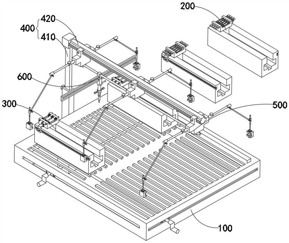
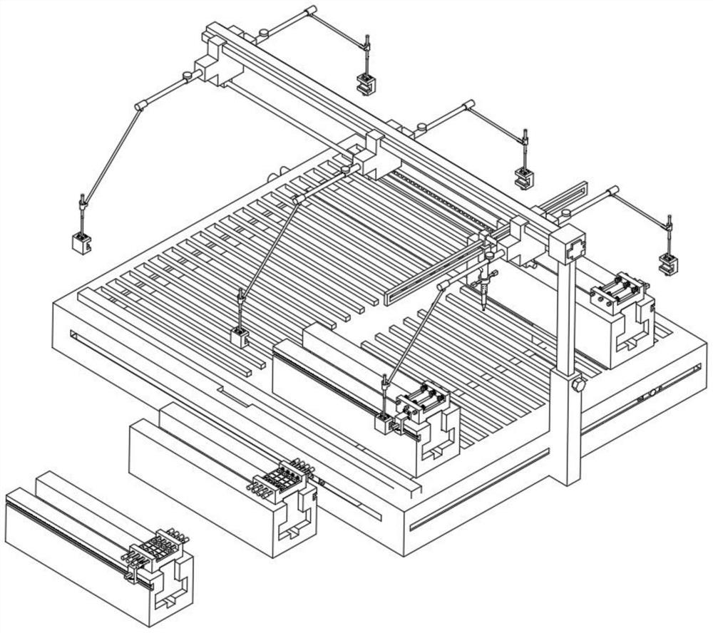
[0056] combine figure 1 , 4 , 7, 12 and 14, the circuit board soldering device for controller production provided by the present invention includes a control combination 100, a second accessory mechanism 200, a first accessory mechanism 300, a lifting combination 400, a fixing mechanism 500 and a spot welding assembly 600, wherein, the lifting assembly 400 is fixedly installed on the outside of the protective outer frame 110 inside the control assembly 100 through its internal lifting pile 410, and the second accessory mechanism 200 and the first accessory mechanism 300 can both pass through the forehead located in the control assembly 100 The T-shaped slider is inserted above the control combination 100, while the fixing mechanism 500 is movably installed on the lifting combination 400 through its internal fixing block 510. In addition, the spot welding assembly 600 is installed on the fixing mechanism 500 through its internal slide bar 610. superior.

[0057] The control a...

Embodiment 2

[0062] As shown in 9, in the above embodiment, slot holes are provided in the middle of the four edges of the protective outer frame 110, and two ends of the first rocker 130 and the second rocker 140 are installed at the same time. The gear of the bar 120 can make the base 210 and the base 310 carry out precise displacement and movement by utilizing the stable movement of the upper gears of the first rocker 130 and the second rocker 140 in the inner teeth of the rack 120. The control combination 100 also includes a The rack 120 in the slot on the inner edge of the protective frame 110 , the first rocker 130 connected in the protective frame 110 , and the second rocker 140 adapted to be installed in the inner cavity of the protective frame 110 .

Embodiment 3

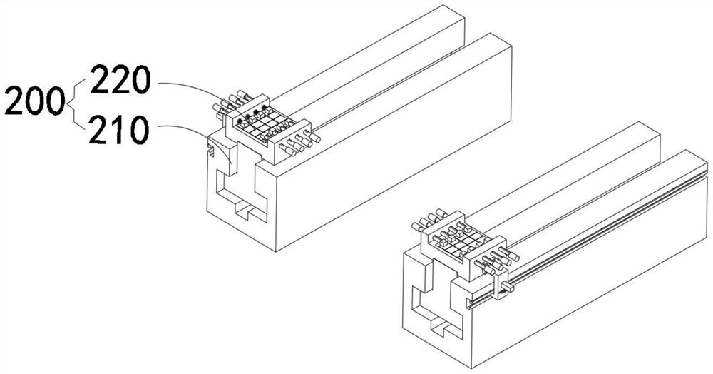
[0064] combine image 3 and 9 As shown, in the above embodiment, the base 210 and the rectangular hole at the bottom of the base 310 are connected to the chute on the top of the protective frame 110 through a T-shaped slider, and combined with the practical method of pressing the internal components of the assembly 220, the base is set 210 is inserted on the T-shaped slider, which can assist the internal parts of the compression combination 220 to quickly move different electronic components under the component surface at the bottom of the circuit board. By setting the base 310 and the coordination combination 320, the resistance in the electronic components The limit is fixed, which can make the silver corner of the bent resistor and its whole be fixed smoothly, and at the same time, under the action of the bar-shaped rack in the outer chute of the base 310, the fixed resistor can be accurately adapted to the position of the pad. At the same time, T-shaped sliders are instal...


PUM


Abstract

The invention discloses a circuit board soldering device for controller production, comprising a control combination, a second fitting mechanism, a first fitting mechanism, a lifting combination, a fixing mechanism and a spot welding assembly. The control combination comprises a protective outer frame, and the second The accessory mechanism includes a pressing combination, and the pressing combination comprises a second sliding block and a spring buckle mounted on the top of the second sliding block. The limit slots of the first rocker and the second rocker on the base and the T-shaped slider at the bottom of the base can ensure that the electronic components fixed on the pressing combination and the coordination combination can be accurately aligned with the bottom surface of the printed circuit board At the same time, the electronic components are pressed by the electromagnet piece, the permanent magnet piece, the first sliding piece and the pressing piece. When the tooth slot on one side moves, it ensures that the electronic components used for spot welding will not be subject to the problem of partial rollover caused by the shaking of the artificial hand.

Description

technical field [0001] The invention relates to the field of circuit board soldering, in particular to a circuit board soldering device for controller production. Background technique [0002] Circuit boards are also called ceramic circuit boards, alumina ceramic circuit boards, etc. The circuit board is a miniaturized and intuitive circuit board, which plays an important role in the mass production of fixed circuits and the optimization of the layout of electrical appliances. According to the development of circuit boards According to the number of layers, circuit boards can be divided into three categories: single-layer boards, double-sided boards and multi-layer circuit boards. The circuit boards are collectively referred to as printed circuit boards. [0003] The printed circuit board is divided into the component surface and the welding surface, and the inside of the welding surface is provided with densely distributed pads. Before the printed circuit board reaches the ...

Claims


Application Information

Patent Timeline
Patent Type & Authority Patents(China)
IPC IPC(8): H05K3/34B23K37/04
CPCH05K3/34H05K2203/04H05K2203/167H05K2203/15H05K2203/1509
Inventor 师后龙
Owner 徐州科悦电子科技有限公司
Learn More