
Clamp tool structure for mechanical and electrical product manufacturing

A technology of electromechanical products and fixtures, which is applied in the direction of manufacturing tools, clamping, positioning devices, etc., can solve the problems of not being able to stably and conveniently clamp objects that need to be clamped, and achieve the effect of easy movement, convenient use, stable and controllable rotation

Pending Publication Date: 2021-01-29
株洲兆能机电科技有限公司
View PDF1 Cites 0 Cited by
  • Summary
  • Abstract
  • Description
  • Claims
  • Application Information

AI Technical Summary

Problems solved by technology

[0005] Aiming at the deficiencies of the prior art, the present invention provides a jig tooling structure for the manufacture of electromechanical products, which has the advantages of rotating and lateral clamping functions of the jig, and can stably and conveniently clamp objects to be clamped, and solves the problem of unstable Convenient clamping of objects to be clamped

Method used


Image

  • Clamp tool structure for mechanical and electrical product manufacturing
  • Clamp tool structure for mechanical and electrical product manufacturing

Examples


Embodiment Construction

[0023] The following will clearly and completely describe the technical solutions in the embodiments of the present invention with reference to the accompanying drawings in the embodiments of the present invention. Obviously, the described embodiments are only some, not all, embodiments of the present invention. Based on the embodiments of the present invention, all other embodiments obtained by persons of ordinary skill in the art without making creative efforts belong to the protection scope of the present invention.

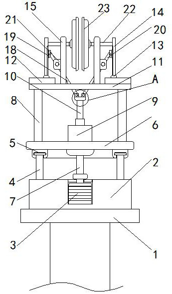
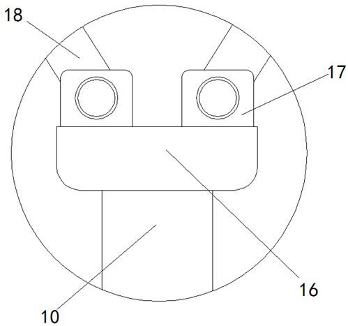
[0024] see Figure 1-2 , a fixture tooling structure for the manufacture of electromechanical products, including a connecting and stabilizing block 1, the connecting and stabilizing block 1 is composed of a support plate at the top and a connecting column at the bottom, and the top of the support plate is provided with a placement slot, and the support plate is connected to the The connection method of the column is welding, and the top of the connecting stab...


PUM


Abstract

The invention relates to the technical field of clamps, and discloses a clamp tool structure for mechanical and electrical product manufacturing. The clamp tool structure comprises a connecting stabilizing block. A motor plate is fixedly connected to the top of the connecting stabilizing block. A motor is fixedly connected to the top of the motor plate. Stabilizing support blocks are fixedly connected to the top of the motor plate. The tops of the stabilizing supporting blocks are rotationally connected with stabilizing blocks. According to the clamp tool structure for mechanical and electrical product manufacturing, the connecting stabilizing block is arranged, so that the whole clamp is fixedly connected conveniently, the motor plate is arranged, the motor plate is cylindrical, a motor groove is formed in the top of the motor plate, and annular grooves with the outer diameters equal to the outer diameters of the stabilizing supporting blocks are formed in the top of the motor plate,so that the motor is fixed and stabilized conveniently; and a rotation transition plate is driven to rotate through rotation of the motor, the purpose of stable and controllable rotation of the rotation transition plate is achieved through the stabilizing effect of the stabilizing supporting blocka and the stabilizing blocka, and use by a user is facilitated.

Description

technical field [0001] The invention relates to the technical field of fixtures, in particular to a fixture tooling structure used in the manufacture of electromechanical products. Background technique [0002] Fixture refers to the device used to fix the processing object in the process of mechanical manufacturing so that it can occupy the correct position to accept construction or inspection. It is also called fixture. In a broad sense, any process in the process is used to quickly and The device that installs the workpiece conveniently and safely can be called a fixture. [0003] With the development of science and technology and the improvement of people's living standards, people's requirements for the convenience of things are getting higher and higher. The previous clamps, such as a clamp proposed by Chinese patent CN101444902B, do not have rotation and horizontal clamps. Therefore, a clamp tooling structure for the manufacture of electromechanical products is propos...

Claims


Application Information

Patent Timeline
IPC IPC(8): B23Q3/06B23Q1/25
CPCB23Q1/25B23Q3/06
Inventor 王树峰李爱东张长青凌可列
Owner 株洲兆能机电科技有限公司
Learn More