
Distributor plate

Pending Publication Date: 2022-09-15
METSO SWEDEN AB
View PDF0 Cites 0 Cited by
  • Summary
  • Abstract
  • Description
  • Claims
  • Application Information

AI Technical Summary

Benefits of technology

This patent describes a rotor design for a machine that changes the position of a distributor plate to control the flow of fluid. The rotor has attachment means that keep the distributor plate in place without needing to pass through it with a bolt or the like. Friction between the distributor plate and the lower plate prevents rotation, and a mounting plate on the lower plate can be easily attached to a rotor boss. The rotor also has a middle plate with protrusions and recesses that make it easier to position the distributor plate. These features make the rotor more user-friendly and efficient for positioning the distributor plate.

Problems solved by technology

However, with current rotors, there may be a problem with the distributor plate being unevenly worn out.
However, a problem with the solution in the prior art document is that fastening means of the distributor plate, or parts of the distributor plate, may have to be loosened before being able to rotate the distributor plate into the new wear position.
Further, if the distributor plate needs to be lifted for rotation, dirt may come in between the lower plate and the distributor plate causing instability of the distributor plate.
Using distributor plates known in the art, the wear on the distributor plate may be uneven and thus, the distributor plate may be worn out differently at different positions of the distributor plate.

Method used


Image

  • Distributor plate
  • Distributor plate
  • Distributor plate

Examples


Embodiment Construction

[0071]The present disclosure will now be described more fully hereinafter with reference to the accompanying drawings, in which currently preferred embodiments of the disclosure are shown. This disclosure may, however, be embodied in many different forms and should not be construed as limited to the embodiments set forth herein; rather, these embodiments are provided for thoroughness and completeness, and to fully convey the scope of the disclosure to the skilled person.

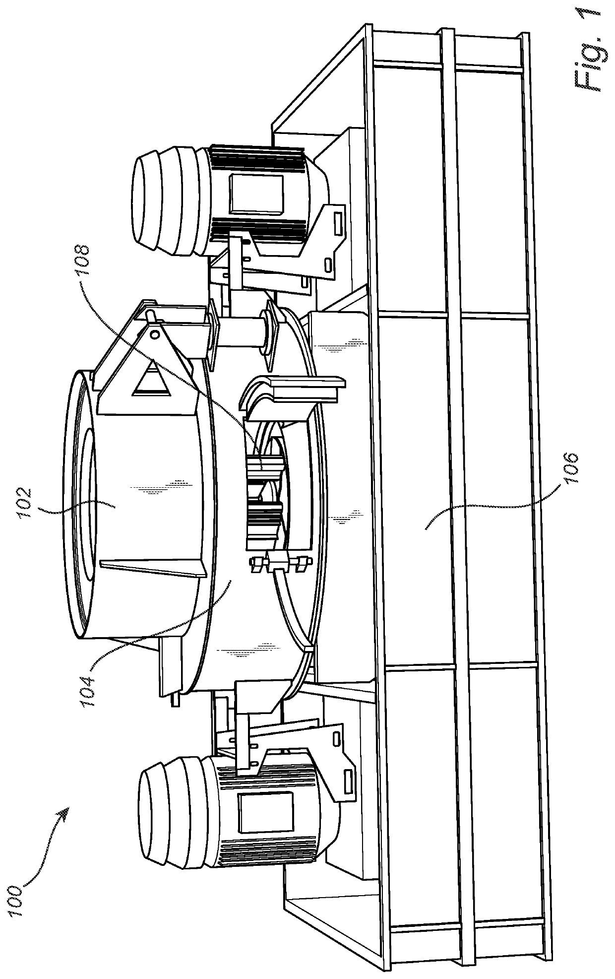
[0072]FIG. 1 illustrates a comminution apparatus 100 for crushing or grinding rock, ore, cement clinker and other hard materials or softer materials by way of example. The comminution apparatus 100 is configured to crush the materials by pushing them by force against metal but also by using the materials fed into the comminution apparatus 100 to crush itself by launching the material against an autogenous layer of crushed material. The comminution apparatus 100 may be a vertical shaft impact crusher.

[0073]The comminu...


PUM


Abstract

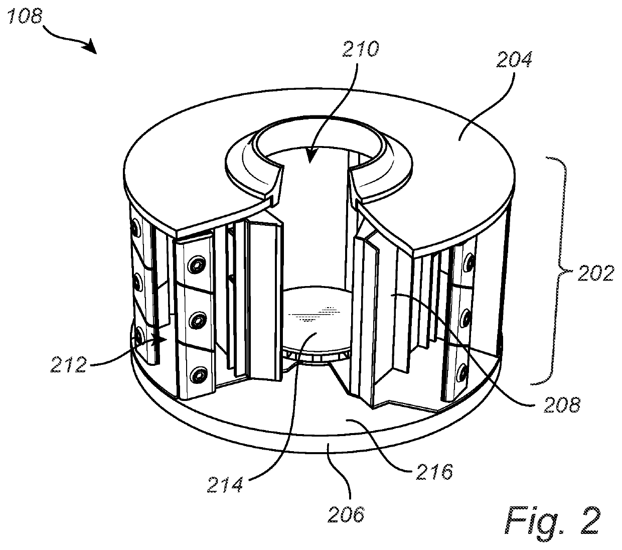
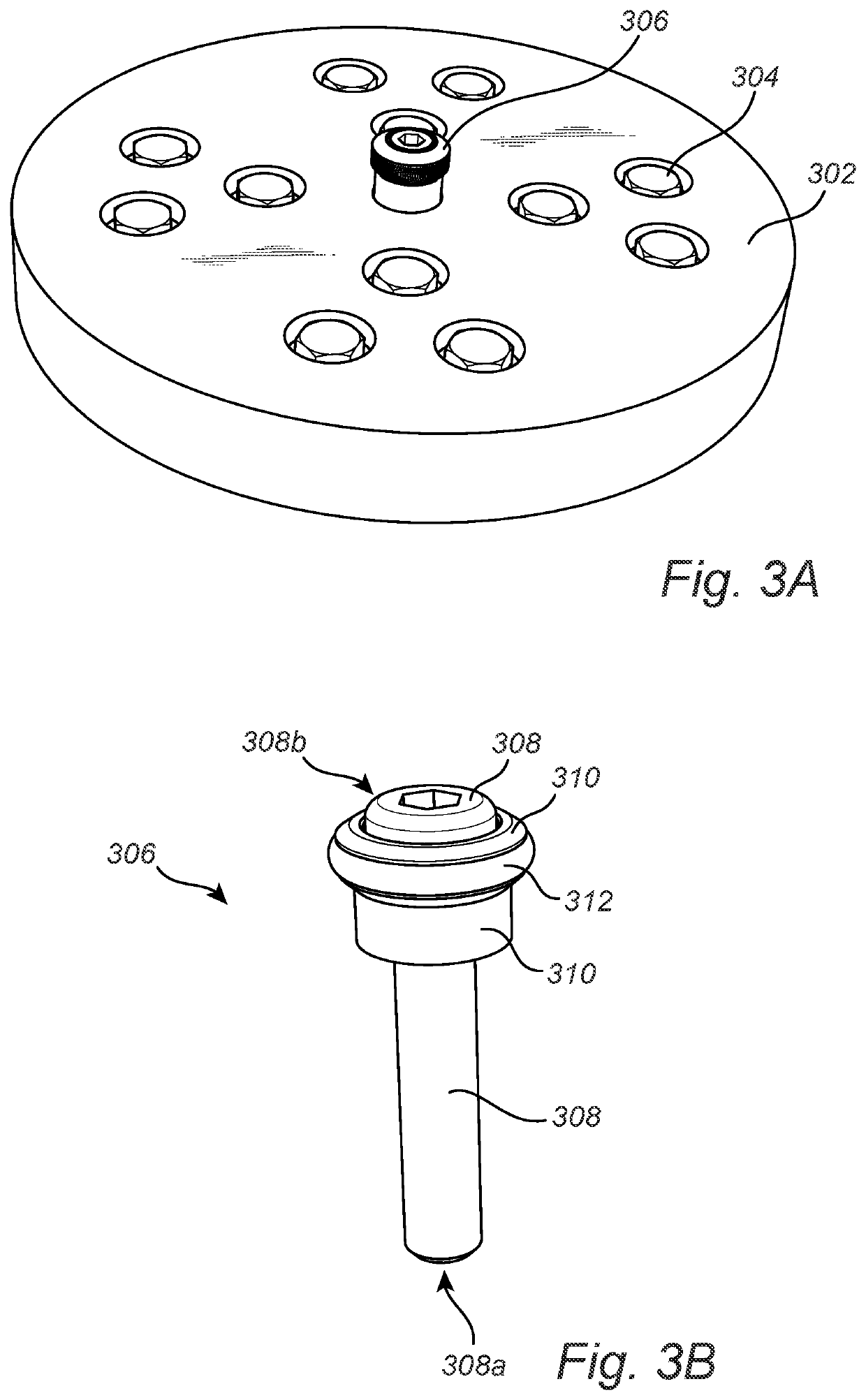
The disclosure relates to a rotor for a comminution apparatus, the rotor comprising: a frame including an upper plate, a lower plate and wall elements; an inlet opening in the upper plate and one or more outlets located between the upper plate and the lower plate; and a distributor plate arranged at an upper surface of the lower plate below said inlet opening wherein the distributor plate is arranged to launch the material towards the surface, wherein the distributor plate comprises a cavity being open at a lower surface of the distributor plate, wherein the rotor further comprises attachment means for maintaining the distributor plate at the upper surface of the lower plate, wherein said attachment means are arranged to frictionally engage with a corresponding surface of the cavity and wherein the attachment means enable the distributor plate to be repositioned into different wear positions.

Description

FIELD OF THE DISCLOSURE[0001]The present disclosure relates to crushing equipment for crushing rock, ore or similar. More specifically, the invention relates to a so-called vertical shaft impact crusher comprising a rotatable distributor plate.BACKGROUND ART[0002]When crushing or grinding rock, ore, cement clinker and other hard or soft materials, vertical shaft impact crushers are used having a rotor rotating around a vertical axis. The material to be crushed is fed through a centrally arranged opening in the rotor. A distributor plate is arranged at an upper surface of a lower plate of the rotor. As the material to be crushed hits the rotating distributor plate, the material will change direction from vertical to horizontal and will be hauled generally radially outwardly and hit an outer crushing surface. The outer crushing surface typically comprising a build-up of material to be crushed created on an inner surface of a crushing chamber creating autogenous crushing. Such autogeno...

Claims


Application Information

Patent Timeline
IPC IPC(8): B02C13/286B02C13/18
CPCB02C13/286B02C13/1835B02C2013/28681B02C13/185B02C13/1814B02C13/2804B02C2013/2808B02C2210/02
Inventor BRINDLE, ELLIOTT
Owner METSO SWEDEN AB
Learn More