
An automatic packaging system for graphite heaters

A graphite heater and automatic packaging technology, which is applied in the direction of pressurized/vaporized packaging, packaging, electric heating devices, etc., can solve the problems of difficulty, easy breakage of electrodes, and easy breakage of products, so as to reduce the force on the edge The effect of size, avoiding excessive size of the press, symmetrical and uniform force

Active Publication Date: 2022-04-22
SINOSTEEL NEW MATERIAL ZHEJIANG
View PDF0 Cites 0 Cited by
  • Summary
  • Abstract
  • Description
  • Claims
  • Application Information

AI Technical Summary

Problems solved by technology

[0003] The graphite heater is an essential component in the thermal field structure of the single crystal furnace. The product at the electrode is relatively thin, and because the product of the graphite heater is brittle, it is easy to break during transportation, especially at the electrode. Therefore, the product The packaging needs to be done well. The existing packaging process is mainly product bagging, vacuuming and sealing. Most of the packaging process is manual operation, and the labor intensity of personnel is relatively high. In addition, most of the graphite heaters are hollow structures, which makes the packaging process more difficult. Large, especially in the vacuuming process, the overall vacuum effect is poor, it is difficult to discharge the air in the packaging, so that the packaging bag does not completely fit the heater, the appearance is not beautiful, and the graphite heater cannot be effectively protected, resulting in the packaging bag being damaged during transportation. It is easy to break, pollute the graphite heater, affect the final use, and the product is easy to break during product transportation and cause the product to be scrapped

Method used


Image

  • An automatic packaging system for graphite heaters
  • An automatic packaging system for graphite heaters
  • An automatic packaging system for graphite heaters

Examples


Embodiment 1

[0061] Such as Figure 4-9 Shown, a kind of automatic packing system with graphite heater, comprises rack 1, also comprises:

[0062] The first conveyor 2, the first conveyor 2 is used to transport the graphite heater 100 to be packaged;

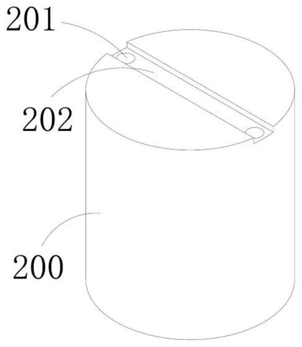
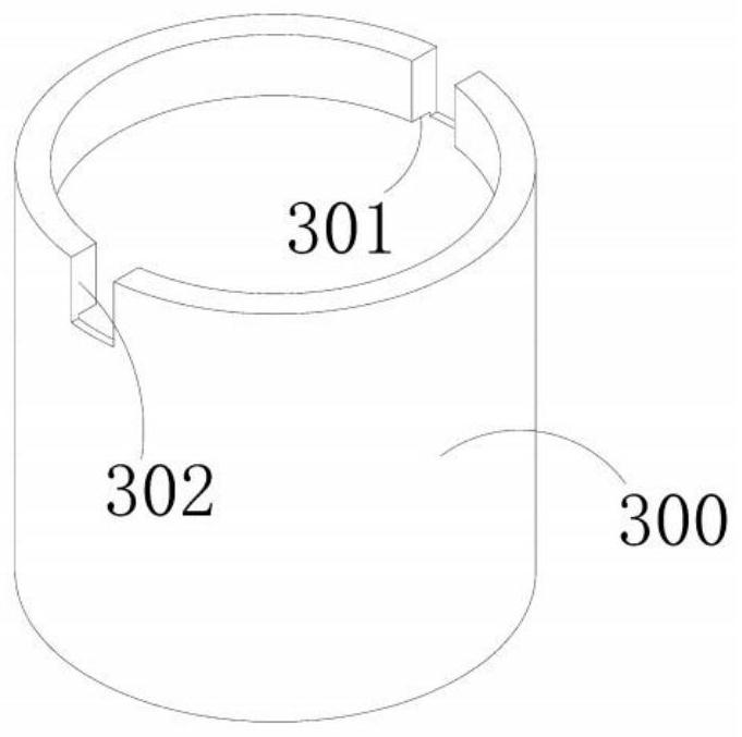
[0063] The second conveyor 3, the second conveyor 3 is used to transport the inner lining 200 and the outer lining 300;

[0064] The 3rd conveyer 4, described 3rd conveyer 4 is used for conveying the graphite heater 100 that packing is finished; One end side of described 3rd conveyer 4 is provided with packing workbench 41, and the both sides of packing workbench 41 are symmetrically arranged There is a guide bracket 411, a guide groove 4111 is provided on the guide bracket 411, a positioning groove 412 is provided on the bottom surface of the packaging workbench 41, and a groove-shaped opening 4121 is provided above the positioning groove 412;

[0065] Manipulator 5, described manipulator 5 is used for grabbing and moving graphite heater ...

Embodiment 2

[0086] Such as Image 6 As shown, the parts that are the same as or corresponding to those in Embodiment 1 adopt the reference numerals corresponding to Embodiment 1. For the sake of simplicity, only the differences between Embodiment 1 and Embodiment 1 are described below; the differences between Embodiment 2 and Embodiment 1 The advantage is that:

[0087] Such as Image 6 As shown, wherein, the manipulator 5 includes a horizontal rotation assembly 51, a vertical telescopic assembly 52 connected with the horizontal rotation assembly 51, a horizontal telescopic assembly 53 connected with the vertical telescopic assembly 52, and arranged on the The second connecting rod assembly 54 at one end of the horizontal telescopic assembly 53 and two clamps 55 symmetrically arranged at one end of the second connecting rod assembly 54 ; the shape of the clamps 55 is matched with the graphite heater 100 .

[0088] It should be noted that a rotating motor is provided at the bottom of the...

Embodiment 3

[0092] Such as Figure 18-20 As shown, the parts that are the same as or corresponding to the first embodiment adopt the corresponding reference numerals of the first embodiment. For the sake of simplicity, only the differences between the first embodiment and the first embodiment are described below; the differences between the third embodiment and the first embodiment The difference is that:

[0093] Such as Figure 18 As shown, as an improvement, the first positioning channel 21 with a groove on the top is provided on the first conveyor 2, and the first positioning channel 21 matches the shape of the graphite heater 100; A second positioning channel 22 with a boss on the top is provided, and the second positioning channel 22 matches the shapes of the inner liner 200 and the outer liner 300 .

[0094] It should be noted that during transportation, the electrodes of the graphite heater are positioned and conveyed through the grooves opened on the top of the first positionin...


PUM


Abstract

The invention provides an automatic packaging system for graphite heaters, which includes a frame, a first conveyor, a second conveyor, a third conveyor, a manipulator, a packaging bag conveying unit, two sets of symmetrically arranged opening units, a pump Vacuum unit and two sets of symmetrically arranged heat-sealing units use the packaging bag conveying unit to automatically load the bag, and the opening unit automatically supports the mouth to realize automatic bagging and opening; the manipulator sequentially puts the inner lining, graphite heater and outer lining into the packaging In the bag, make the inner lining and outer lining completely wrap the graphite heater to prevent the graphite heater from being damaged due to the impact of external force. The vacuum nozzle passes through the electrode hole of the graphite heater and inserts it into the through hole opened on the inner lining to vacuumize. , so that the graphite heater can completely discharge the air during the vacuuming process, so that the packaging bag can completely fit the surface of the outer lining, make the packaging more beautiful, the transportation process is more stable, reduce the labor intensity of personnel, and improve the packaging quality.

Description

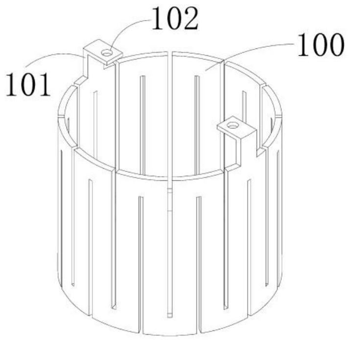
technical field [0001] The invention relates to the technical field of packaging equipment, in particular to an automatic packaging system for graphite heaters. Background technique [0002] Such as figure 1 As shown, the shape is barrel-shaped, the heating plate is a circuit, and there are electrodes on one side of the graphite heater. [0003] The graphite heater is an essential component in the thermal field structure of the single crystal furnace. The product at the electrode is relatively thin, and because the product of the graphite heater is brittle, it is easy to break during transportation, especially at the electrode. Therefore, the product The packaging needs to be done well. The existing packaging process is mainly product bagging, vacuuming and sealing. Most of the packaging process is manual operation, and the labor intensity of personnel is relatively high. In addition, most of the graphite heaters are hollow structures, which makes the packaging process more...

Claims


Application Information

Patent Timeline
Patent Type & Authority Patents(China)
IPC IPC(8): B65B5/10B65B7/02B65B31/04B65B35/16B65B35/22B65B43/30B65B43/54B65B51/10H05B3/14
CPCH05B3/145B65B5/105B65B7/02B65B35/16B65B35/22B65B43/30B65B43/54B65B31/048B65B31/042B65B51/10
Inventor 黄岱杨辉刘升肖绍懿
Owner SINOSTEEL NEW MATERIAL ZHEJIANG
Learn More