Wire coil paying-off device and method

A wire pay-off device and wire reel technology, applied in the field of electric power, can solve the problems of non-universal use, low use efficiency, heavy pay-off device, etc., and achieve the effects of convenient carrying, reasonable design and simple structure.

Pending Publication Date: 2021-01-29
ZAOZHUANG POWER SUPPLY COMPANY OF STATE GRID SHANDONG ELECTRIC POWER +1
View PDF7 Cites 1 Cited by
  • Summary
  • Abstract
  • Description
  • Claims
  • Application Information

AI Technical Summary

Problems solved by technology

In electrical construction, it is necessary to install the wire reel on a special pay-off rack; while the existing wire reel display racks are relatively traditional in design and cannot be used universally, and different types of wire reels are often used in electrical construction
In addition, the traditional pay-off device is very heavy, has low efficiency, and is inconvenient to carry and carry.

Method used


Image

  • Wire coil paying-off device and method
  • Wire coil paying-off device and method

Examples


Embodiment Construction

[0013] The present invention will be further elaborated below in conjunction with accompanying drawing and specific embodiment:

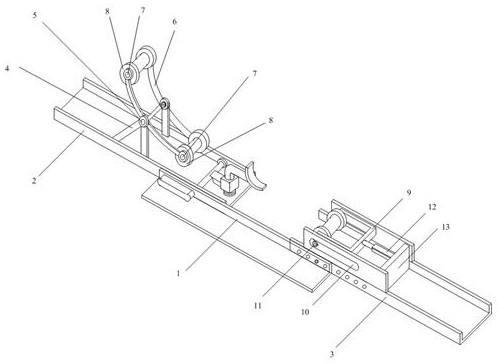
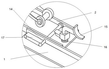
[0014] Such as Figure 1-2 As shown, a reel pay-off device includes connecting angle steel 1, fixed channel steel 2, movable channel steel 3, fixed bracket 4, rotating shaft A5, arc connecting arm 6, rotating shaft B7, concave pulley 8, U-shaped connection Rod 9, slide rail 10, rotating shaft C11, horizontal jack 12, support plate 13, characterized in that: the left side of the connecting angle steel 1 is welded to the fixed channel steel 2, and the right side of the connecting angle steel 1 is connected to the movable channel steel 3 through Bolt connection, the top of the fixed channel steel 2 is equipped with a fixed bracket 4, and the top of the fixed bracket 4 is equipped with an arc-shaped connecting arm 6 through the rotating shaft A5, and two rotating shafts B7 are symmetrically installed at both ends of the arc-shaped connecting arm 6 , a ...


PUM


Abstract

The invention discloses a wire coil paying-off device and method. The wire coil paying-off device comprises connecting angle steel, a U-shaped connecting rod, a sliding rail, a rotating shaft C and ahorizontal jack; the left side of the connecting angle steel is connected with fixed channel steel in a welded mode; the right side of the connecting angle steel is connected with movable channel steel through bolts; a fixed support is mounted at the top of the fixed channel steel; an arc-shaped connecting arm is mounted at the top of the fixed support through a rotating shaft A; two rotating shafts B are symmetrically mounted at the two ends of the arc-shaped connecting arm; concave pulleys are mounted on the rotating shafts B; the sliding rail is arranged at the top of the movable steel channel; the concave pulleys and the U-shaped connecting rod are connected into the sliding rail through rotating shafts C; the horizontal jack is mounted on the right side of the U-shaped connecting rod;and the other end of the horizontal jack is connected with the supporting plate welded in the movable channel steel. The paying-off device is simple in structure, reasonable in design, capable of achieving free paying-off and braking at any time, capable of being used for mounting different types of wire coils, convenient to carry and transport and applicable to the wire coils in different sizesand heights.

Description

technical field [0001] The invention relates to a wire reel pay-off device, which belongs to the field of electric power. Background technique [0002] In the process of electrical construction, it is often necessary to lay out wires or cables, and the wires or cables are wound on the reel for easy retraction. In electrical construction, it is necessary to install the wire reel on a special pay-off rack; while the existing wire reel display racks are relatively traditional in design and cannot be used universally, and different types of wire reels are often used in electrical construction. In addition, the traditional pay-off device is very heavy, has low efficiency, and is inconvenient to carry and carry. Contents of the invention [0003] The object of the present invention is to provide a wire reel pay-off device to solve the problems raised in the above-mentioned background technology. [0004] To achieve the above object, the present invention provides the following...

Claims


Application Information

Patent Timeline
Patent Type & Authority Applications(China)
IPC IPC(8): B65H49/32B65H49/18
CPCB65H49/324B65H49/18B65H2701/34
Inventor 李强杨斌李全建高畅王正波王丙辉马新燕徐可新陈晶晶杜昊阳郝清翔梁盟马灿马兆国梁波郭光成李正刚杜玮马平颜大智付娅岳苓高文祥闫洪林李显达赵联政
Owner ZAOZHUANG POWER SUPPLY COMPANY OF STATE GRID SHANDONG ELECTRIC POWER
Why Eureka
Try Eureka