Device mounted on upper part of floor drain
A floor drain and floor technology, applied in water supply installations, indoor sanitary plumbing installations, waterway systems, etc., can solve problems such as food residues, odors, and slow drainage of floor drains, and achieve the effect of effective cleaning and increased excretion
- Summary
- Abstract
- Description
- Claims
- Application Information
AI Technical Summary
Problems solved by technology
Method used
Image

Examples
Embodiment Construction
[0016] The present invention will be further described in detail below in conjunction with the accompanying drawings and specific embodiments.
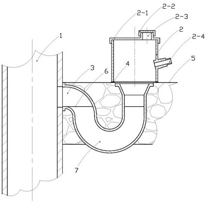
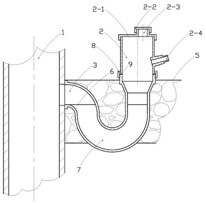
[0017] like figure 1 As shown, it is a schematic structural diagram of an embodiment of a device installed above the floor drain of the present invention. Visible in the picture:
[0018] The left side of the illustration is the pipe 1 of the vertical drainage system; the floor drain 3 is arranged on the right side of the pipe 1; there is a gap on the right pipe wall of the pipe 1 corresponding to the opening on the side of the floor drain 3; the floor drain 3 in the illustration belongs to In a typical trap form, the existence of the trap 7 enables the liquid surface 6 to effectively block the odor of the pipeline 1; a device body 2 is provided above the upper opening of the floor drain 3; the device body 2 passes through the adhesive 4 is fastened on the ground 5; the right side of the device body 2 shown in the figure is provided...
PUM
 Abstract
Description
Claims
Application Information
PatSnap Eureka turns technology decisions into work you can execute. Powered by our Innovation Knowledge Graph, it runs expert workflows across engineering, life sciences, materials and intellectual property. Get your review-ready output in minutes.


