A double self-elevating external climbing frame for super high-rise buildings
A building and self-lifting technology, applied in the direction of building structure, building, scaffolding supported by house structure, etc., can solve the problems of low strength of support system, need to improve safety, inconvenient for installation and disassembly of climbing frame, etc. The effect of safety and stability improvement
- Summary
- Abstract
- Description
- Claims
- Application Information
AI Technical Summary
Problems solved by technology
Method used
Image
Examples
Embodiment 1
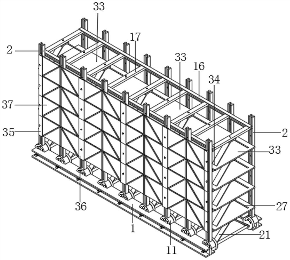
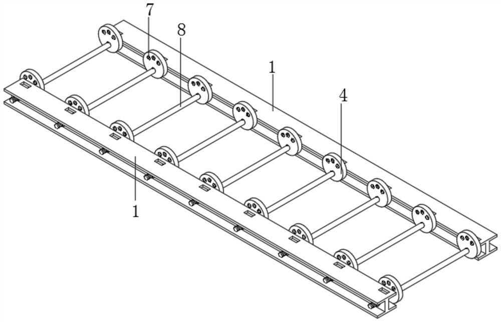
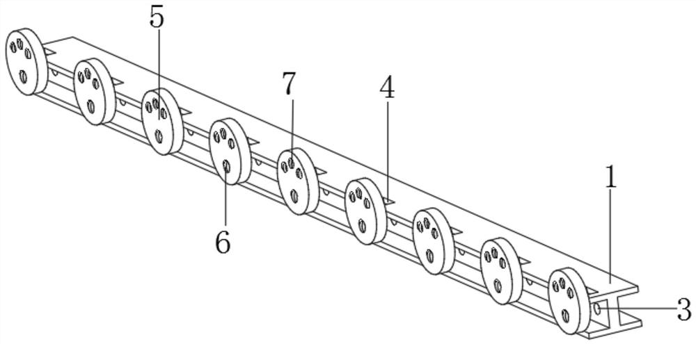
[0047] Such as figure 1 , figure 2 , image 3 , Figure 4 , Figure 5 , Image 6 , Figure 7 , Figure 8 , Figure 9 , Figure 10 with Figure 11 The shown double self-elevating external climbing frame of a super high-rise building includes two sets of bottom I-beams 1 and vertical I-beams 2, and the centers of the bottom I-beams 1 are provided with perforations 3 at equal intervals. , the top of the I-beam 1 at the bottom of the frame is equidistantly provided with connecting moment grooves 4, the spacing of the connecting moment grooves 4 is the same as that of the perforations 3, the number of connecting moment grooves 4 is equal to the number of perforations 3, and the frame bottom I-shaped The side of the steel 1 is fixed with connecting discs 5, and the connecting discs 5 are equidistantly arranged on the side of the I-beam 1 at the bottom of the frame, and the spacing and quantity of the arrangement are the same as those of the perforations 3. The connecting d...
Embodiment 2
[0049] Embodiment 2 is a further improvement to Embodiment 1.
[0050] Such as Figure 12 , Figure 13 with Figure 14 As shown, there is a bottom support between the lowermost horizontal piece and the I-beam 1 at the bottom of the frame, and the bottom support is arranged at equal intervals between the bottom horizontal piece and the I-beam 1 at the bottom of the frame. The spacing and quantity are the same as the spacing and quantity of the perforations 3. The bottom support includes two sets of first slanting braces 21 and first connecting plates 22, and a first matching positioning hole 23 is opened in the center of the top of the first connecting plates 22. , the bottom end of the first diagonal bracing plate 21 is connected with the first connecting block 24, and the bottom end of the first connecting block 24 is provided with an arc groove 25. , the maximum horizontal distance of the first connecting block 24 of the two groups is equal to the length of the smooth par...
Embodiment 3
[0052] Embodiment 3 is a further improvement to Embodiment 2.
[0053] Such as Figure 15 , Figure 16 , Figure 17 with Figure 18 As shown, a scaffold board 33 is laid above the horizontal member, and the top of the scaffold board 33 is provided with a second slant brace 27 and a first slant brace 21 to cooperate with the oblique groove 34, and the vertical I-beam 2 outer groove surface on one side Side fixtures 35 and inner fixtures 36 are installed, the side fixtures 35 are L-shaped structures, and the interior fixtures 36 are T-shaped structures. The slot 38 runs through the top of the side fixing part 35 and the top of the inside fixing part 36. A protective side plate 37 is installed between the side fixing part 35 and the inside fixing part 36. The protective side plate 37 is inserted into the side fixing part 35 and the inside fixing part 36. In the mounting groove 38 between, the center of side fixing part 35 side and inside fixing part 36 one sides is provided w...
PUM
 Abstract
Description
Claims
Application Information
 - R&D
- Intellectual Property
- Life Sciences
- Materials
- Tech Scout
- Unparalleled Data Quality
- Higher Quality Content
- 60% Fewer Hallucinations
Browse by: Latest US Patents, China's latest patents, Technical Efficacy Thesaurus, Application Domain, Technology Topic, Popular Technical Reports.
© 2025 PatSnap. All rights reserved.Legal|Privacy policy|Modern Slavery Act Transparency Statement|Sitemap|About US| Contact US: help@patsnap.com


