Intelligent lock

A technology of smart locks and lock frames, applied in the field of smart locks, can solve the problems of increasing the unlocking resistance of keys and laborious manual unlocking, etc., and achieve the effects of reducing resistance, facilitating production and assembly, and having a simple structure.

Pending Publication Date: 2021-01-29
浙江亿龙智能科技有限公司
View PDF0 Cites 3 Cited by
  • Summary
  • Abstract
  • Description
  • Claims
  • Application Information

AI Technical Summary

Problems solved by technology

Most of the existing anti-theft door locks can be automatically unlocked by a motor, and can also be manually unlocked by a key. The user can freely choose the unlocking method, which is convenient for users. When unlocking, the reduction gear set is required to increase the torque, but when the user unlocks manually with the key, the reduction gear set and the motor will greatly increase the resistance of the key unlocking, which makes manual unlocking very laborious

Method used


Image

  • Intelligent lock
  • Intelligent lock
  • Intelligent lock

Examples


Embodiment Construction

[0034] The present invention will be further described below in conjunction with accompanying drawing with specific embodiment:

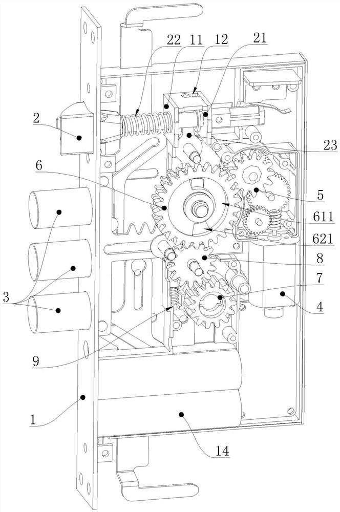
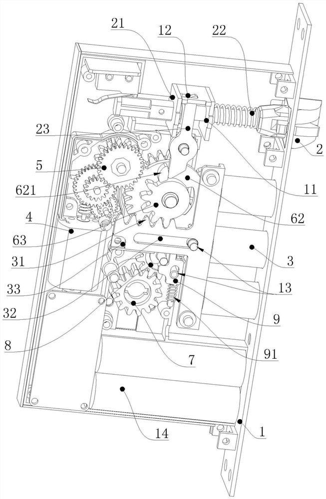
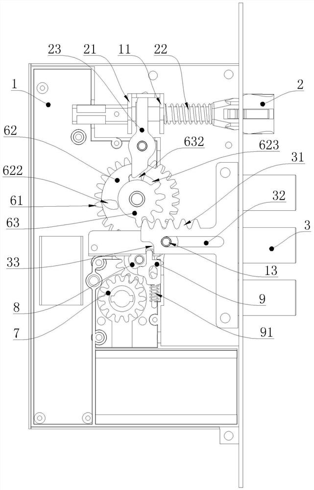
[0035] See Figure 1 to Figure 11As shown, a kind of intelligent lock, comprises lock frame 1, and lock frame 1 is provided with deadbolt 2 and lock head 3 for anti-theft slidingly, and described lock frame 1 is provided with the motor 4 that is used to drive lock head 3 to move and A control circuit for controlling the movement of the motor 4. A gear set is arranged between the motor 4 and the dead bolt 2. The motor 4 drives the gear set to move and drives the dead bolt 2 to slide relative to the lock frame 1. The gear set includes a gear lock cylinder 7 and a The reduction gear set 5 connected to the motor 4, the intermittent gear set 6 connected with the dead bolt 2 is arranged between the gear lock cylinder 7 and the reduction gear set 5;

[0036] The intermittent gear set 6 includes a coaxial first gear 61 and a second gear 62 that drives the ...


PUM


Abstract

The invention belongs to the technical field of safe-guard door locks, and particularly relates to an intelligent lock. The intelligent lock comprises a lock rack, wherein a lock tongue and lock heads, which are used for safe guard, are slidingly arranged in the lock rack, a motor used for driving the lock heads to move is arranged on the lock rack, a gear set is arranged between the motor and thelock tongue, the motor drives the gear set to move, and drives the lock tongue to slide relative to the lock rack, and the gear set comprises a gear lock cylinder, a reduction gear set and an intermittent gear set. The intermittent gear set comprises a first gear and a second gear, the first gear and the second gear are connected with the reduction gear set and the gear lock cylinder respectively, a first arc-shaped groove is formed in the first gear, a second bulge is arranged on the second gear, the second bulge is arranged in the first arc-shaped groove in a penetrating mode, when the lockis opened by a user through a mechanical key, the mechanical key controls the gear lock cylinder to rotate, and the lock tongue is controlled by the second gear to shrink towards the interior of thelock rack, so that the second bulge slides in the first arc-shaped groove. The purpose is to provide the intelligent lock which is convenient to use and can be opened manually and effortlessly.

Description

technical field [0001] The invention belongs to the technical field of anti-theft door locks, in particular to an intelligent lock. Background technique [0002] With the development and progress of society, people's requirements for the safety and management of locks are constantly improving. Traditional mechanical locks can no longer meet people's needs in terms of safety and management. Therefore, anti-theft doors are widely used. It can resist abnormal opening under certain conditions, has a certain safety protection performance and meets the corresponding anti-theft safety level. Its safety level is directly related to the lives and property of thousands of households. Anti-theft doors have become an indispensable product for every household, which can ensure the safety of people's lives and property. Most of the existing anti-theft door locks can be automatically unlocked by a motor, and can also be manually unlocked by a key. The user can freely choose the unlocking ...

Claims


Application Information

Patent Timeline
Patent Type & Authority Applications(China)
IPC IPC(8): E05B47/00E05B63/14E05B15/00
CPCE05B15/00E05B47/0012E05B63/146E05B2047/002E05B2047/0058
Inventor 朱斌
Owner 浙江亿龙智能科技有限公司
Why Eureka
Try Eureka